4 VD 14,5/12-1 SRW
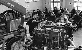
The 4 VD 14,5/12-1 SRW is an inline four-cylinder diesel engine produced by the VEB IFA Motorenwerke Nordhausen from 1967 to 1990. The engine was one of the standard modular engines for agricultural and industrial use in the Comecon-countries. Approximately one million units were made.
| 4 VD 14,5/12-1 SRW | |
|---|---|
 | |
| Overview | |
| Manufacturer | VEB IFA Motorenwerke Nordhausen |
| Production | 1967–1990 |
| Layout | |
| Configuration | Straight-4 |
| Displacement | 6560 cm³ |
| Cylinder bore | 120 mm |
| Piston stroke | 145 mm |
| Valvetrain | OHV |
| Combustion | |
| Operating principle | Diesel |
| Supercharger | None |
| Turbocharger | None |
| Fuel system | M-System direct injection |
| Fuel type | DK1 or DK3 45 CN (TGL 4938) |
| Cooling system | Water-cooled |
| Output | |
| Power output | 92 kW at 2300 min−1 |
| Torque output | 422 Nm at 1350 min−1 |
| Chronology | |
| Predecessor | 4 KVD 14,5/12 |
| Successor | None |
Technical description
The 4 VD 14,5/12-1 SRW is a water-cooled four-stroke diesel engine with four inline cylinders. The Fuel is injected with a mechanical direct injection system. The bore is 120 mm, the stroke is 145 mm, the displacement is 6560 cm³. The firing order is 1-3-4-2. The standard version of the engine produces 92 kW and has a torque of 422 Nm. The combustion chamber system (M-System) was licensed by MAN. The engine was produced in the versions 4 VD 14,5/12-1 SRW and 4 VD 14,5/12-2 SRW, the later revision was built primary for the NVA. The name 4 VD 14,5/12-1 stands for 4-Zylinder-Viertakt-Diesel, Hub 14,5 cm / Bohrung 12 cm, Baureihe 1, Stehend, Reihe, Wassergekühlt.[1] (4 cylinders-four-stroke-diesel, stroke 14,5 cm / bore 12 cm, version 1, inline, water-cooled).
Crankcase
The crankcase is made of grey cast iron, both the crankshaft and the camshaft are supported in five bearings. The center bearing of the crankshaft is an axial bearing. The camshaft is driven by a connecting gear, which also drives the injection pump. The housing of the crankshaft bearing contains the housing of the oil pump. Some versions of the engine are equipped with a speedometer gear assembly, which is connected to the injection pump drive.
Crankshaft, pistons and cylinders

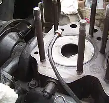
The engine has a forged crankshaft, supported in changeable thin-wall bearing shells. The journals of the crankshaft and the connecting rods are polished and induction hardened. The counter-weights are screwed on the center and outer crank arms. The flywheel is connected to the power take-off side of the engine with screws. The gear drive side of the crankshaft is equipped with a gear, which drives the oil pump and the gear which drives the camshaft. The connecting rods are forged and weight-balanced. While the small connecting rod bore has a bearing pressed into the bore, the crank-sided bore of the connecting rod has a thin-wall bearing. For lubrication and cooling of the connecting rods they have small oil-ducts. Oil is pressed in the ducts from a nozzle at the upper side of the connecting rod. The piston journals are secured with two circlips and are bathed in oil. A heat resistant light-metal-alloy is used for the cast pistons. The combustion chamber is integrated into the piston. For compression, the pistons have two piston rings which slots are cast into the piston. The pistons are also equipped with an oil control ring. The cylinder liners are made of centrifugally cast iron, two rubber rings seal the liners off from the crankcase. The engine has two cast iron cylinder blocks with two cylinders; every block has a head, which makes two cylinder heads.
Valvetrain and fuel Injection
The engine uses OHV. The camshaft is gear driven by the connecting gear as described earlier. Every cylinder head has four overhead valves, which are activated by tappets, pushrods and rocker arms. The injection nozzles are connected to the cylinder heads with a flange. The valve seats are made of a heat-resistant material and unlikely to be worn out. The injection duct is grooved.
Cooling
The engine has a water cooling system with a centrifugal pump, which is driven from the crankshaft with a belt; it runs always. A thermostat controls the water amount. Starting at 80 °C the water is pumped into the water cooler, before this temperature level, it circulates in the engine block only to increase the engine temperature fast. The engine fan runs always, except from later versions of the engine which have a fan with an electro-magnetic clutch, which is activated at 92 °C by a temperature sensor.
Lubrication
The oil pump in the crankshaft bearing housing creates oil pressure and pumps the oil from the oil sump through the engine. In the main oil flow a sieve filter cleans the oil, the secondary oil flow has a centrifugal oil filter. Some engine variants don't have a sieve filter but a paper filter instead. The lubrication of the injection pump and the air compressor may either be attached to the main oil flow or be attached to a separate oil lubrication system. For oil cooling the engine has an involute heat exchanger or a shell and tube heat exchanger. Shell and tube heat exchangers are found mostly in engines for the IFA W50.
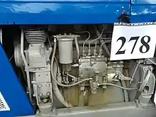
Fuel system

Air compressor
Fuel filter housing
Inline injection pump
Speed controller
Fuel is pumped from an inline injection pump to the injection nozzles. The injection pump is a pump with a rotational speed controller, fuel filter and a pump clutch. Some engines have an injection timing device instead of the pump clutch. The rotational speed controller is either an all-speed controller or an idle speed controller. The speed controllers are driven by the camshaft of the injection pump. The idle speed controller does affect the idle and redline speed only, while the all-speed controller affects every rotation speed. For fuel filtering a paper filter is used.
Air compressor
Engines for vehicles are equipped with an air compressor, to supply compressed air for the brakes. It is an air-cooled single-cylinder air-compressor driven by a belt. The air-intake is next to the engine intake manifold. The crankcase is not divided, the crankshaft is forged and has two ball bearings. The pushrod is housed in a needle bearing, the piston journal has a plain bearing pressed into the push rod bore. The piston has two piston rings and one oil control ring. Lubrication is done by a dry sump lubrication system, the compressor valves are poppet valves.
Cold start system
The cold start system has a solenoid valve and a glow filament which are connected in series. When starting the engine, diesel fuel comes through the solenoid valve and gets heated at the glow filament, the diesel fuel evaporates. It gets ignited at the last glow filament. The heat increases the temperature of the air from the intake manifold and makes it possible to start the engine unless the temperature level is not below -15 °C.
Electrical system
The engine is fitted with a starter motor, which is mounted on the crankcase at the exhaust side with securing clips. It is a 24 V direct current series-wound motor with a rated power of 4 kW. The three-phase current alternator has an electronic control unit. It is mounted on the exhaust side of the engine and is driven by a belt from the crankshaft.
Technical specifications
The engine was produced in seven basic variants. No specific names were used, instead engines were categorized after their intended use.
| Engine | Displacement | Compression ratio | Rated power at 1/min | Torque at 1/min | Specific fuel consumption | Minimum fuel consumption | Specific oil consumption |
|---|---|---|---|---|---|---|---|
| Trucks (for example IFA W50) | 6,6 l (6560 cm³) | 18:1 | 92 kW/2300 | 422 Nm/1350 | 238 g/kWh | 218 g/kWh | 125 g/h |
| ZT 300 | 74 kW/1800 | 100 g/h | |||||
| ZT 320 | 230 g/kWh | ||||||
| E 512 | 77 kW/2000 | 392 Nm/1350 | 238 g/kWh | 125 g/h | |||
| E 514 | 85 kW/2000 | 422 Nm/1400 | |||||
| Stationary engine A | 48 kW/1500 | 353 Nm/1200 | 222 g/kWh | 100 g/h | |||
| Stationary engine B | 58 kW/1800 |
Otto version
In the mid-1980s, a prototype of an Otto cycle engine based upon the 4 VD 14,5/12-1 SRW was made. This engine, designated the 4 VOG 14,5/12 SRW, (4 cylinder, four-stroke, Otto, gas, stroke 14.5 cm, bore 12 cm, upright standing, in-line engine, water cooled) had spark ignition, a throttle valve, and was specifically designed for running on gaseous fuels, such as biogas and methane.[2]
Bibliography
- Authors of the VEB IFA-Motorenwerke Nordhausen: Dieselmotor 4 VD 14,5/12-1 SRW Reparaturhandbuch, 2nd edition, VEB Fachbuchverlag, Leipzig 1987 (German)
- Boch, Rudolf: Geschichte und Zukunft der deutschen Automobilindustrie. Franz Steiner Verlag Stuttgart. 2001. ISBN 3-515-07866-5 (German)
- Peter Kirchberg: Plaste, Blech und Planwirtschaft: Die Geschichte des Automobilbaus in der DDR, Nicolaische Verlagsbuchhandlung, 2005 ISBN 978-3894792596 (German)
References
- Ministerium des Inneren der DDR: Versorgungsdienste – Typenkatalog für Fahrzeuge. Pages 11 and 12. Published on July 18th 1978. Access date 20th of August 2015 (german)
- G. Reinhold, G. Pfeiffer, I. Irmscher, R. Jäkel: Inbetriebnahme eines Stationärmotors 4 VOG 14,5/12 SRW mit ungereinigtem Biogas, in Agrartechnik, volume 36, number 12, December 1986, pp. 559