5DX
The 5DX was an automated X-ray inspection robot, which belonged to the set of automated test equipment robots and industrial robots utilizing machine vision. The 5DX was manufactured by Hewlett Packard, then later Agilent Technologies when HP was split into Hewlett Packard and Agilent Technologies in 1999. The 5DX performed a non-destructive structural test using X-ray laminography (tomography) to take 3D images of an assembled printed circuit board using 8-bit grayscale to indicate solder thickness. It was used in the assembled printed circuit board (PCB) electronics manufacturing industry to provide process feedback to a surface mount technology assembly line, as well as defect capture.
The 5DX was one of several tools used by many companies in the electronics manufacturing services sector to provide a means of inspecting both the visible and hidden solder connections between the printed circuit boards and components attached to those printed circuit boards. These solder connections (also known as solder joints) are referred to as PCB interconnects.
5DX technology
The 5DX used a gantry robot to move the assembled printed circuit board underneath an X-ray source to be able to image the components' joints that require inspection. The positioning of board was guided with the use of Computer Aided Design (CAD) data, which represented the outer layers of a printed circuit board's electrical design.
The 5DX system used classical laminography to create an x-ray image “slice”, or image plane that will be distinct from other image planes on the object to be imaged. A slice will remove obstructions above or below the plane of focus so that only the regions of interest remain. X-Ray systems that use methods such as laminography ( or the now more commonly used tomography ) are marketed as “3D” x-ray systems. X-Ray systems that do not use these methods and only produce a transmissive shadow image are marketed as “2D” systems.
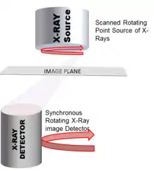
Classical laminography[1] is based on a relative motion of the x-ray source, the detector and the object. The x-ray source and the detector are moved synchronously in circles 180 degrees out of phase with each other as shown in the figure.

Due to that correlated motion, the location of the projected images of points within the object moves also. Only points from a particular slice, the so-called focal plane, will be always projected at the same location onto the detector and therefore imaged sharply. Object structures above and below the focal plane will move as the rotation occurs. Because of that, they are not imaged sharply and they will blur to a grey background image. This requires precise height data, created by laser mapping the surface of the board. The focal plane is approximately .003 inches (.076 mm) deep.
Rotational laminography requires a complex system to produce the rotating x-ray source, rotate the image detector and maintain synchronization between source and detector. In addition, the laminography systems require a system to map the surface of the object to be imaged. Product to be imaged is rarely perfectly flat.[2] The 5DX system used a laser mapping system to measure bow and twist so that the effects could be compensated for in the imaging process. In the 5DX system the rotating x-ray source is produced by scanning a high energy electron beam around an x-ray producing target integral to the x-ray tube. The rotating detector is implemented by rotating an x-ray sensitive screen mechanically and projecting the image into a high sensitivity digital camera. Aside from the electro-mechanical complexity, the main disadvantages of classical laminography are the background intensity that reduces the contrast resolution and the fact that in each measurement only one slice is imaged sharply. All other slices have to be inspected consecutively by displacing the object vertically. Classical laminography has been replaced by computed tomography (CT) or computed laminography in more modern automated x-ray systems.
History of the 5DX
Agilent Technologies (now Keysight Technologies) the OEM of the 5DX and follow on product, the X6000, exited the automated inspection market in March 2009. Both the 5DX and the X6000 were discontinued at that time. Even though the systems have been out of production for several years, a significant number remain in use.
Product Revision History
- 3DX (end of life) originally developed by Four Pi Systems which was acquired by Hewlett Packard.
- 5DX Series I (end of life)
- 5DX Series 2/II/2L (end of life)
- 5DX Series 3
- 5DX Series 5000
- X6000 (also known as the X6K ) the evolution of the 5DX product line which used the more advanced digital tomosynthesis.
References
- Digital computed Laminography and Tomosynthesis - Functional Principles and Industrial Applications; S. Gondrom, S. Schröpfer, FhG ITFP, Saarbrücken, D; International Symposium on Computerized Tomography for Industrial Applications and Image Processing in Radiology March, 15 - 17, 1999 Berlin, Germany
- IPC-A-600G, Acceptability of Printed Circuit Boards, Section 2.11 Flatness
External links
- Digital computed laminography and tomosynthesis - functional principles and industrial applications
- Agilent Technologies
- Medalist 5DX Automated X-ray Inspection System
- IC Inspection for Defect-Free Connections***DEAD LINK***