Behavior tree
Behavior trees are a formal, graphical modelling language used primarily in systems and software engineering. Behavior trees employ a well-defined notation to unambiguously represent the hundreds or even thousands of natural language requirements that are typically used to express the stakeholder needs for a large-scale software-integrated system.[1][2][3][4]
Overview
The amount of detail in the large number of natural language requirements for a large-scale system causes short-term memory overload[1][5] and may create a barrier that prevents anyone from gaining a deep, accurate and holistic understanding of the system needs.[6] Also, because of the use of natural language, there are likely to be many ambiguities, aliases, inconsistencies, redundancies and incompleteness problems associated with the requirements information.[3] This adds further to the uncertainty and complexity. Generally, at best, a few people understand parts of the system or situation well, but no one has other than a superficial understanding of the whole – that is, the detailed integrated behavior of the system.
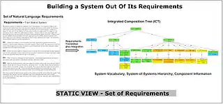
The behavior tree representation, (with the help of the composition tree[7] representation that resolves alias and other vocabulary problems with large sets of requirements) allows people to avoid short-term memory overload and produce a deep, accurate, holistic representation of system needs[1] that can be understood by all stakeholders because it strictly uses the vocabulary of the original requirements. Because the behavior tree notation uses a formal semantics, for any given example, it already is, or can be made executable.
Behavior tree forms

Single and composite or integrated behavior tree forms are both important in the application of behavior trees in systems and software engineering.
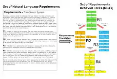
- Requirement behavior trees: Initially, individual requirement behavior trees (RBTs) are used to capture all the fragments of behavior in each individual natural language requirement by a process of rigorous, intent-preserving and vocabulary-preserving translation. The translation process can uncover a range of defects in original natural language requirements.
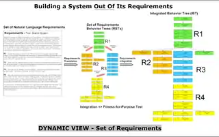
- Integrated behavior trees: Because a set of requirements imply the integrated behavior of a system, all the individual requirement behavior trees can be composed to construct an integrated behavior tree (IBT) that provides a single holistic view of the emergent integrated behavior of the system. This enables the building of the integrated behavior of a system out of its requirements.[8] An analogy to help describe this process is the transition from a randomly arranged set of jigsaw puzzle pieces to putting each of the pieces in its appropriate place. When we do this, we see each piece of information in its intended context and we see the pieces of information as a whole and the emergent properties of the whole.
Having all the requirements converted to behavior trees (RBTs) is similar to having all the pieces for a jigsaw puzzle randomly spread out on a table - until we put all the pieces together we cannot see the emergent picture and whether any pieces are missing or do not fit. Constructing an integrated behavior tree (IBT) allows us to do this.[2][3]
Behavior engineering process
- Representation used - (critical)
- BEHAVIOR TREES provide a vehicle for growing a shared understanding of a complex system.
- The role of the COMPOSITION TREE in the overall process is to provide a vehicle for overcoming the imperfect knowledge associated with the large set of requirements for a system.
- Process used - (critical)
- BEHAVIOR ENGINEERING uses behavior trees to control complexity while growing a shared understanding of a complex system.
- That shared, holistic understanding of a complex system, because it integrates the requirements, shows the emergent behavior of the system implied by requirements.

History
Behavior trees and the concepts for their application in systems and software engineering were originally developed by Dromey[2][3][9][10] with first publication of some of the key ideas in 2001.[11] Early publications on this work used the terms "genetic software engineering" and "genetic design" to describe the application of behavior trees. The reason for originally using the word genetic was because sets of genes, sets of jigsaw puzzle pieces and sets of requirements represented as behavior trees all appeared to share several key properties:
- they contained enough information as a set to allow them to be composed – with behavior trees this allows a system to be built out of its requirements
- the order in which the pieces were put together was not important – with requirements this aids coping with complexity
- when all the members of the set were put together the resulting integrated entity exhibited a set of important emergent properties.
For behavior trees important emergent properties include
- the integrated behavior of the system implied by the requirements
- the coherent behavior of each component referred to in the requirements.
These genetic parallels, in another context, were originally spelled by Woolfson,[12] (A. Woolfson, Living Without Genes, Flamingo, 2000)
Further weight for use of the term genetic came from eighteenth-century thinker Giambattista Vico, who said, "To understand something, and not merely be able to describe it, or analyse it into its component parts, is to understand how it came into being – its genesis, its growth … true understanding is always genetic".[13] Despite these legitimate genetic parallels it was felt that this emphasis led to confusion with the concept of genetic algorithms. As a result, the term behavior engineering was introduced to describe the processes that exploit behavior trees to construct systems. The term "behavior engineering" has previously been used in a specialized area of Artificial Intelligence - robotics research. The present use embraces a much broader rigorous formalization and integration of large sets of behavioral and compositional requirements needed to model large-scale systems.
Since the behavior tree notation was originally conceived a number of people from the DCCS (Dependable Complex Computer-based Systems Group – a joint University of Queensland, Griffith University research group) have made important contributions to the evolution and refinement of the notation and to the use of behavior trees. Members of this group include: David Carrington, Rob Colvin, Geoff Dromey, Lars Grunske, Ian Hayes, Diana Kirk, Peter Lindsay, Toby Myers, Dan Powell, John Seagrott, Cameron Smith, Larry Wen, Nisansala Yatapanage, Kirsten Winter, Saad Zafar, Forest Zheng.
Probabilistic timed behavior trees have recently been developed by Colvin, Grunske and Winter so that reliability, performance and other dependability properties can be expressed.[14]
Key concepts
Behavior tree notation
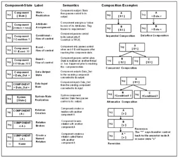
A behavior tree is used to formally represent the fragment of behavior in each individual requirement. Behavior for a large-scale system in general, where concurrency is admitted, appears abstractly as a set of communicating sequential processes. The behavior tree notation captures these composed component-states in a simple tree-like form.
Behavior is expressed in terms of components realizing states and components creating and breaking relations. Using the logic and graphic forms of conventions found in programming languages, components can support actions, composition, events, control-flow, data-flow, and threads.[3]
Traceability tags (see Section 1.2 of behavior tree notation[15]) in behavior tree nodes link the formal representation to the corresponding natural language requirement. Behavior trees accurately capture behavior expressed in the natural language representation of functional requirements. Requirements behavior trees strictly use the vocabulary of the natural language requirements but employ graphical forms for behavior composition in order to eliminate risk of ambiguity. By doing this they provide a direct and clearly traceable relationship between what is expressed in the natural language representation and its formal specification.[16]
A basis of the notation is that behavior is always associated with some component. Component-states which represent nodes of behavior are composed sequentially or concurrently to construct a behavior tree that represents the behavior expressed in the natural language requirements. A behavior tree with leaf nodes may revert (symbolized by adding the caret operator ^) to an ancestor node to repeat behavior, or start a new thread (symbolized by two carets ^^).
A behavior tree specifies state changes in components, how data and control is passed between components and how threads interact. There are constructs for creating and breaking relations. There are also constructs for setting and testing states of components as well as mechanisms for inter-process communication that include message passing (events), shared variable blocking and synchronization.
For a complete reference to behavior tree notation, version 1.0, see: Behavior Tree Notation v1.0 (2007)[15]
Semantics
The formal semantics of behavior trees is given via a process algebra and its operational semantics.[17] The semantics has been used as the basis for developing simulation, model checking and failure modes and effects analysis.[17][18][19]
Requirements translation

Requirements translation is the vehicle used to cross the informal-formal barrier. Consider the process of translation for requirement R1 below. The first tasks are to identify the components (bold), identify the behaviors (underline) and identify indicators of the order (italics) in which behaviors take place. The corresponding behavior tree can then be constructed.
What is clear from the outcome of this process is that apart from pronouns, definite articles, etc., essentially all the words in the sentences that contribute to the behavior they describe have been accounted for and used.
Requirements integration
Once the set of requirements are formalized as individual requirement behavior trees, two joint properties of systems and requirements need to be exploited in order to proceed with composing the integrated behavior tree:
- In general, a fragment of behavior expressed by a requirement always has associated with it a precondition which needs to be satisfied before the behavior can take place (this precondition may or may not be expressed in the requirement).
- If the requirement is really part of the system then some other requirement in the set must establish the precondition needed in (1).
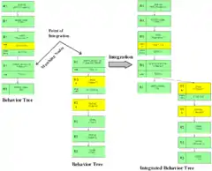
- For requirements represented as behavior trees this amounts to finding where the root node of one tree occurs in some other behavior tree and integrating the two trees at that node.
The example below illustrates requirements integration for two requirements, R1 and R3. In other words, it shows how these two requirements interact.
Operations on integrated behavior trees
Once an integrated behavior tree has been composed, there are a number of important operations that can be performed upon it.
Inspection: defect detection and correction
In general, many defects become much more visible when there is an integrated view of the requirements[1] and each requirement has been placed in the behavior context where it needs to execute. For example, it is much easier to tell whether a set of conditions or events emanating from a node is complete and consistent. The traceability tags[15] also make it easy to refer back to the original natural-language requirements. There is also the potential to automate a number of defect and consistency checks on an integrated behavior tree.[20]
When all defects have been corrected and the IBT is logically consistent and complete it becomes a model behavior tree (MBT) which serves as a formal specification for the system’s behavior that has been constructed out of the original requirements. This is the clearly defined stopping point for the analysis phase. With other modelling notations and methods (for instance, with UML) it is less clear-cut when modelling can stop.[21] In some cases, parts of a model behavior tree may need to be transformed to make the specification executable. Once an MBT has been made executable it is possible to carry out a number of other dependability checks.
Simulation
A model behavior tree can be readily simulated to explore the dynamic properties of the system. Both a symbolic tool and a graphics tool have been constructed to support these activities.[22][23]
Model-checking
A translator has been written to convert a model behavior tree into the "actions systems" language. This input can then be fed into the SAL Model-checker[24][25] in order to allow checks to be made as to whether certain safety and security properties are satisfied.[18][26]
Failure mode and effects analysis (FMEA)
Model-checking has often been applied to system models to check that hazardous states cannot be reached during normal operation of the system.[27] It is possible to combine model-checking with behavior trees to provide automated support for failure mode and effects analysis (FMEA).[18] The advantage of using behavior trees for this purpose is that they allow the formal method aspects of the approach to be hidden from non-expert users.
Requirements change
The ideal that is sought when responding to a change in the functional requirements for a system is that it can be quickly determined:
- where to make the change,
- how the change affects the architecture of the existing system,
- which components of the system are affected by the change, and
- what behavioral changes will need to be made to the components (and their interfaces) that are affected by the change of requirements.[4]
Because a system is likely to undergo many sets of changes over its service time, there is also a need to record, manage and optimize the system’s evolution driven by the change sequence.
A traceability model, which uses behavior trees as a formal notation to represent functional requirements, reveals change impacts on different types of design constructs (documents) caused by the changes of the requirements.[28] The model introduces the concept of evolutionary design documents that record the change history of the designs. From these documents, any version of a design document as well as the difference between any two versions can be retrieved. An important advantage of this model is that the major part of the procedure to generate these evolutionary design documents can be supported by automated tools.[20]
Code generation and execution
The behavior tree representation of the integrated behavior of the system affords several important advantages as an executable model. It clearly separates the tasks of component integration from the task of individual component implementation. The integrated behavior of the system that emerges from integrating the requirements can be used as a foundation to create a design by applying design decisions. The result is a design behavior tree (DBT):[3] an executable multithreaded component integration specification that has been built out of the original requirements.
Behavior tree models are executed in a virtual machine called the behavior run-time environment (BRE). The BRE links together components using middleware,[29] allowing components to be independent programs written in one of several languages that can be executed in a distributed environment. The BRE also contains an expression parser that automatically performs simple operations to minimize the amount of code required to be manually implemented in the component.
The implementation of components is supported by views that are automatically extractable from the DBT. These views provide the component behavior trees (CBTs) of individual components together with the interfaces of individual components. This information, together with the information in the integrated composition tree (ICT) captured about each individual component, provides the information that is needed to implement each individual component.
Several BRE’s can be linked together to form complex systems using a system-of-systems construct and the behavior engineering component integration environment (BECIE). BECIE is also used to monitor and control the behavior tree models being executed within a BRE, similar to supervisory control and data acquisition (SCADA) systems used in industrial process control.
Executable behavior trees have been developed for case studies[21] including automated train protection,[30] mobile robots with dynamic object following, an ambulatory infusion pump[19] and traffic light management systems. A version of the BRE suited for embedded systems (eBRE) is also available that has reduced functionality to tailor it to small-footprint microcontrollers.
Applications
Behavior tree modelling can and has been applied to a diverse range of applications over a number of years. Some of the main application areas are described below.
Large-scale systems
Modeling large-scale systems with large sets of natural-language requirements have always been the major focus for trialling behavior trees and the overall behavior engineering process. Conducting these evaluations and trials of the method has involved work with a number of industry partners and government departments in Australia. The systems studied have included a significant number of defense systems, enterprise systems, transportation systems, information systems, health systems and sophisticated control systems with stringent safety requirements. The results of these studies have all been commercial-in-confidence. However the results of the extensive industry trails[5][6] with Raytheon Australia are presented below in the Industry Section. What all this work has consistently shown is that by translating requirements and creating dynamic and static integrated views of requirements a very significant number of major defects are discovered early, over and above the defects that are found by current industry best-practice.[31][32]
Embedded systems
Failure of a design to satisfy a system’s requirements can result in schedule and cost overruns.[33] If there are also critical dependability issues, not satisfying system requirements can have life-threatening consequences.[34] However, in current approaches, ensuring requirements are satisfied is often delayed until late in the development process during a cycle of testing and debugging.[35] This work describes how the system development approach, behavior engineering, can be used to develop software for embedded systems.[26] The result is a model-driven development approach that can create embedded system software that satisfies its requirements, as a result of applying the development process.
Hardware–software systems
Many large-scale systems consist of a mixture of co-dependent software and hardware. The different nature of software and hardware means they are often modelled separately using different approaches. This can subsequently lead to integration problems due to incompatible assumptions about hardware/software interactions.[30] These problems can be overcome by integrating behavior trees with the Modelica, mathematical modelling approach.[30] The environment and hardware components are modelled using Modelica and integrated with an executable software model that uses behavior trees.
Role-based access control
To ensure correct implementation of complex access control requirements, it is important that the validated and verified requirements are effectively integrated with the rest of the system.[36] It is also important that the system can be validated and verified early in the development process. An integrated, role-based access control model has been developed.[37] The model is based on the graphical behavior tree notation, and can be validated by simulation, as well as verified using a model checker. Using this model, access control requirements can be integrated with the rest of the system from the outset, because: a single notation is used to express both access control and functional requirements; a systematic and incremental approach to constructing a formal behavior tree specification can be adopted; and the specification can be simulated and model checked. The effectiveness of the model has been evaluated using a case study with distributed access control requirements.[36]
Biological systems
Because behavior trees describe complex behavior, they can be used for describing a range of systems not limited to those that are computer-based.[38] In a biological context, BTs can be used to piece together a procedural interpretation of biological functions described in research papers, treating the papers as the requirements documents as described above. This can help to construct a more concrete description of the process than is possible from reading only, and can also be used as the basis for comparing competing theories in alternative papers. In ongoing research, the behavior tree notation is being used to develop models of the brain function in rats under fear conditioning.
Game AI modeling
While BTs have become popular for modeling the artificial intelligence in computer games such as Halo[39] and Spore,[40] these types of trees are very different from the ones described on this page, and are closer to a combination of hierarchical finite state machines or decision trees. Soccer-player modeling has also been a successful application of BTs.[41][42]
Model Based Testing
[43] is an approach to software testing that requires testers to create test models from requirements of Software Under Test (SUT). Traditionally, UML state charts, FSMs, EFSMs, Flow charts are used as the modeling language. Recently, an interesting approach in which Event-Driven Swim Lane Petri Net (EDSLPN) is used as the modeling language also appears. Behavior tree notation should be considered as a good modeling notation to MBT also, and it has a few advantages among other notations:
- It has the same expressiveness level as UML state charts and EDSLPN
- It is intuitive to use as a modeling notation due to its graphical nature
- Each behavior tree node has a requirement tag, this makes creating a traceability matrix from requirement to test artifact a piece of cake
Such an attempt has been made here.[44] The MBTester is composed of a modeler and a test case generation engine. Business owners or testers translate their requirements into behavior trees using the modeler, and then (optionally) integrate a few related behavior trees into a composite one. A behavior tree can be fed into the backend engine to generate test cases, test scripts, and test data automatically.
Scalability and industry applications
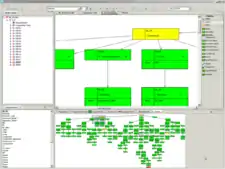

The first industry trials to test the feasibility of the method and refine its capability were conducted in 2002. Over the last three years a number of systematic industry trials on large-scale defence, transportation and enterprise systems have been conducted.[5][31] This work has established that the method scales to systems with large numbers of requirements but also that it is important to use tool support[22][45] in order to efficiently navigate and edit such large integrated views of graphical data. Several main results have come out of this work with industry. On average, over a number of projects, 130 confirmed major defects per 1000 requirements have consistently been found after normal reviews and corrections have been made.[31] With less mature requirements sets much higher defect rates have been observed.
An important part of this work with industry has involved applying the analysis part of the method to six large-scale defence projects for Raytheon Australia. They see the method as "a key risk mitigation strategy, of use in both solution development and as a means of advising the customer on problems with acquisition documentation".[32][46] An outcome of these industry trials has been the joint development[6] with Raytheon Australia of an industry-strength tool to support the analysis, editing and display of large integrated sets of requirements.[45] More extensive details of industry findings can be found on the Behavior Engineering website.[47]
Dr Terry Stevenson (chief technical officer, Raytheon Australia) and Mr Jim Boston (senior project manager Raytheon Australia), Mr Adrian Pitman from the Australian Defence Materiel Organization, Dr Kelvin Ross (CEO, K.J.Ross & Associates) and Christine Cornish (Bushell & Cornish) have provided the special opportunities needed to support this research and to conduct the industry trials[5][31] and live project work. This work has been supported by the Australian Research Council – ARC Centre for Complex Systems and funds received from industry.
Benefits, advantages
As a behavior modelling representation, behavior trees have a number of significant benefits and advantages:
- They employ a well-defined and effective strategy for dealing with requirements complexity, particularly where the initial needs of a system are expressed using hundreds or thousands of requirements written in natural language. This significantly reduces the risk on large-scale projects.[31]
- By rigorously translating then integrating requirements at the earliest possible time they provide a more effective means for uncovering requirements defects than competing methods.[31][32]
- They employ a single, simple notation[15] for analysis, specification and to represent the behavior design of a system.
- They represent the system behavior as an executable integrated whole.
- They build the behavior of a system out of its functional requirements in a directly traceable way which aids verification and validation.[22][37]
- They can be understood by stakeholders without the need for formal methods training. By strictly retaining the vocabulary of the original requirements this eases the burden of understanding.
- They have a formal semantics,[17] they support concurrency, they are executable and they can be simulated, model-checked and used to undertake failure mode and effects analysis.[18]
- They can be used equally well to model human processes, to analyse contracts,[38] to represent forensic information, to represent biological systems, and numerous other applications. In each case they deliver the same benefits in terms of managing complexity, and seeing things as a whole. They can also be used for safety critical systems,[19] embedded systems[26] and real-time systems.[49][50][51]
Criticisms, disadvantages
- For small textbook level examples, their tree-like nature means that the graphic models produced are sometimes not as compact as statechart or state machine behavior specifications.
- Tool support is needed to navigate the very large integrated behavior trees for systems that have hundreds or thousands of requirements.
- For group walkthroughs of very large systems good display facilities are needed.
- There is a need to provide additional sophisticated tool support to fully exploit integrated behavior tree models.
See also
References
- Dromey, R.G. 2007. Principles for Engineering Large-Scale Software-Intensive Systems
- R.G.Dromey, "Formalizing the Transition from Requirements to Design" Archived 25 July 2011 at the Wayback Machine, in "Mathematical Frameworks for Component Software – Models for Analysis and Synthesis", Jifeng He, and Zhiming Liu (Eds.), World Scientific Series on Component-Based Development, pp. 156–187, (Invited Chapter) (2006)
- R.G.Dromey, From Requirements to Design: Formalizing the Key Steps Archived 25 July 2011 at the Wayback Machine, (Invited Keynote Address), SEFM-2003, IEEE International Conference on Software Engineering and Formal Methods, Brisbane, Sept. 2003, pp. 2–11.
- Wen, L., Dromey, R.G. 2007. From Requirements Change to Design Change: A Formal Path
- Boston, J. 2008. Raytheon Australia supports pioneering systems research Archived 15 September 2009 at the Wayback Machine
- Raytheon Australia, 2008. Understanding grows on Behavior Trees Archived 15 September 2009 at the Wayback Machine
- Behavior Engineering. Composition Trees Archived 2 March 2009 at the Wayback Machine
- Winter, K. 2007. Formalising Behaviour Trees with CSP
- R.L.Glass, "Is This a Revolutionary Idea or Not" Archived 25 July 2011 at the Wayback Machine, Communications of the ACM, Vol. 47(11), pp. 23–25, Nov. 2004.
- R.G.Dromey, "Climbing Over the ‘No Silver Bullet’ Brick Wall" Archived 25 July 2011 at the Wayback Machine, IEEE Software, Vol. 23, No. 2, pp. 118–120, (March 2006)
- R.G.Dromey, Genetic Software Engineering - Simplifying Design Using Requirements Integration, IEEE Working Conference on Complex and Dynamic Systems Architecture, Brisbane, Dec 2001.
- A. Woolfson, Living Without Genes, Flamingo, 2000, ISBN 0-00-255618-9
- Berlin, I. The Crooked Timber of Humanity: Chapters in the History of Ideas, Ed., H.Hardy, Princeton University Press, 1998 ISBN 0-691-05838-5
- Colvin, R., Grunske, L., Winter, K. 2007 Probabilistic Timed Behavior Trees Archived 25 July 2011 at the Wayback Machine
- Behavior Tree Group, ARC Centre for Complex Systems, 2007.Behavior Tree Notation v1.0 (2007)
- Dromey, R.G. "Genetic Design: Amplifying Our Ability to Deal With Requirements Complexity" Archived 25 July 2011 at the Wayback Machine, in S.Leue, and T.J. Systra, Scenarios, Lecture Notes in Computer Science, LNCS 3466, pp. 95–108, 2005.
- Colvin, R., Hayes, I.J. 2006 A Semantics for Behavior Trees
- L.Grunske, P.Lindsay, N.Yatapanage, K.Winter, An Automated Failure Mode and Effect Analysis Based on High-Level Design Specification with Behavior Trees, Fifth International Conference on Integrated Formal Methods (IFM-2005), Eindoven, The Netherlands, 2005.
- Zafar, S. and Dromey, R. G., (2005), Integrating Safety and Security Requirements into Design of an Embedded System. Archived 25 July 2011 at the Wayback Machine Asia-Pacific Software Engineering Conference 2005, 15–17 December, Taipei, Taiwan. IEEE Computer Society Press. pp. 629–636.
- Smith, C., Winter, K., Hayes, I., Dromey, R.G., Lindsay, P., Carrington, D.: An Environment for Building a System Out of Its Requirements, 19th IEEE International Conference on Automated Software Engineering, Linz, Austria, Sept. (2004).
- Dromey, R.G. Using Behavior Trees to Model the Autonomous Shuttle System Archived 25 July 2011 at the Wayback Machine, 3rd International Workshop on Scenarios and State Machines: Models, Algorithms, and Tools (SCESM04) ICSE Workshop W5S, Edinburgh, 25 May 2004
- L.Wen, R.Colvin, K.Lin, J.Seagrott, N.Yatapanage, R.G.Dromey, 2007, "Integrare, a Collaborative Environment for Behavior-Oriented Design", in Proceedings of the Fourth International Conference on Cooperative Design, Visualization and Engineering, LNCS 4674, pp. 122–131, 2007
- C. Sun, S. Xia, D. Sun, D. Chen. H.F. Shen, W. Cai: "Transparent adaptation of single-user applications for multi-user real-time collaboration", ACM Transactions on Computer-Human Interaction, Vol. 13, No.4, December 2006, pp. 531–582.
- Bensalem, S., Ganesh, V., Lakhnech, Y., Muñoz, C., Owre, et al.: "An Overview of SAL", Fifth NASA Langley Formal Methods Workshop (LFM 2000), 2000, pp. 187–196.
- Rushby, J. Automated Formal Methods 2006 AFM-2006, Automated Formal Methods 2006, Seattle, August 2006, pp. 6–7.
- Zafar, S. and Dromey, R. G., 2005. Managing Complexity in Modelling Embedded Systems. Archived 25 July 2011 at the Wayback Machine Systems Engineering/Test and Evaluation Conference 2005, 7–9 November, Brisbane, Australia
- Grunske, L., Colvin, R., Winter, K. Probabilistic Model-Checking Support for FMEA Quantitative Evaluation of Systems. QEST 2007. Fourth International Conference on the Quantitative Evaluation of Systems, 17-19 Sept. 2007 pp. 119–128
- Wen, L., Dromey, R.G. 2005. Architecture Normalization for Component-Based Systems Archived 25 July 2011 at the Wayback Machine Proceedings of the 2nd International Workshop on Formal Aspects of Component Software FACS'05, pp. 247–261.
- RTI Inc. 2007 "Meeting Real-Time Requirements in Integrated Defense Systems", RTI White Paper Archived 20 September 2008 at the Wayback Machine.
- Myers, T., Fritzson, P., Dromey, R.G. 2008. Seamlessly Integrating Software & Hardware Modelling for Large-Scale Systems. 2nd International Workshop on Equation-Based Object-Oriented Languages and Tools (EOOLT 2008), Cyprus, July 2008. pp. 5–15.
- Powell, D. 2007. Requirements Evaluation Using Behavior Trees - Findings from Industry Archived 25 July 2011 at the Wayback Machine
- Boston, J., (Raytheon Australia), Behavior Trees - How they improve Engineering Behaviour?, 6th Annual Software and Systems Engineering Process Group Conference (SEPG 2008), Melbourne, Aug. 2008.
- Barker, D. 2000. Requirements modeling technology: a vision for better, faster, and cheaper systems. Proceedings from VHDL International Users Forum Fall Workshop, 2000. pp. 3–6.
- Leveson, N. G. Safeware: System Safety and Computers: [a guide to preventing accidents and losses caused by technology]. Addison-Wesley Publishing Company, 1995. ISBN 0-201-11972-2
- Futrell, R. T., Shafer, D.F., Shafer, L.I. Quality Software Project Management (Software Quality Institute Series). Prentice Hall, 2002 ISBN 0-13-091297-2
- Zafar, S. Colvin, R., Winter, K., Yatapanage, N., Dromey, R.G. Early Validation and Verification of a Distributed Role-Based Access Control Model. 14th Asia-Pacific Software Engineering Conference, Nagoya, Japan, December 2008. pp. 430–437.
- Zafar, S., K.Winter, R.Colvin, R.G.Dromey, "Verification of an Integrated Role-Based Access Control Model" Archived 25 July 2011 at the Wayback Machine, 1st International Workshop - Asian Working Conference on Verified Software (AWCVS'06), pp 230-240, Macao, Oct. 2006.
- Milosevic, Z., Dromey, R.G. On Expressing and Monitoring Behavior in Contracts, EDOC 2002, Proceedings, 6th International Enterprise Distributed Object Computing Conference, Lausanne, Switzerland, Sept. 2002, pp. 3-14.
- Damian Isla Handling Complexity in the Halo 2 AI.
- Chris Hecker My Liner Notes for Spore
- Xiao-Wen Terry Liu and Jacky Baltes An Intuitive and Flexible Architecture for Intelligent Mobile Robots 2nd International Conference on Autonomous Robots and Agents December 13–15, 2004 Palmerston North, New Zealand
- Yukiko Hoshino, Tsuyoshi Takagi, Ugo Di Profio, and Masahiro Fujita Behavior description and control using behavior module for personal robot
- Model Based Testing (MBT) Model-based testing
- MBTester
- Phillips, V., (Raytheon Australia), "Implementing a Behavior Tree Analysis Tool Using Eclipse Development Frameworks", Australian Software Engineering Conference (ASWEC’08), Perth, March 2008
- McNicholas, D., (Raytheon Australia), 2007. Behavior Engineering Industry Benefits
- Behavior Engineering. Behavior Engineering website Archived 1 March 2009 at the Wayback Machine
- For further details see:
- Raytheon Australia - Behavior Trees Joint Development Archived 15 September 2009 at the Wayback Machine
- "Implementing a Behavior Tree Analysis Tool Using Eclipse Development Frameworks" Vincent Phillips, Raytheon Australia.
- Behavior Trees - How they improve Engineering Behaviour? Jim Boston, Raytheon Australia.
- Raytheon Australia supports pioneering systems research Archived 15 September 2009 at the Wayback Machine
- Lin, K., Chen, D., Sun, C., Dromey, R.G., A Constraint Maintenance Strategy and Applications in real-time Collaborative Environments, 2nd International Conference on Cooperative Design, Visualization and Engineering (CDVE2005), 2005.
- Lin, K., Chen, D., Dromey, R.G., Sun, CZ.: Multi-way Dataflow Constraint Propagation in Real-time Collaborative Systems Archived 25 July 2011 at the Wayback Machine, IEEE, The 2nd International Conference on Collaborative Computing: Networking, Applications and Worksharing (CollaborateCom 2006), Atlanta, Georgia, USA, Nov, 2006.
- Grunske, L., Winter, K., Colvin, R., "Timed Behavior Trees and their application to verifying real-time systems" Archived 18 November 2008 at the Wayback Machine, Proceedings of 18th Australian Conference on Software Engineering (AEWEC 2007), April 2007, accepted for publication.