Constraint (computer-aided design)
In engineering design, particularly in the use of computer-aided drafting and design, in the creation of 3D assemblies and multibody systems, the plural term "constraints" refers to demarcations of geometrical characteristics between two or more entities or solid modeling bodies; these delimiters are intentional in defining diverse properties of theoretical physical position and motion, or displacement. In addition, 2D sketches -including the ones used to create extrusions and solid bodies- can also be constrained.

There are several constraints that may be applied between the entities or bodies depending much on their actual natural geometry; sometimes these are also referred to as ’’mates’’ and include: collinearity, perpendicularity, tangency, symmetry, coincidency and parallelity among other ways of establishing the orientation of the entity. Also, a constraint on two (or more) lines may be added so these are equal in length; in the same manner, the diameter of circles can be set to have the same dimension. Moreover, a solid model can also be set to be locked or fixed in space. Depending on the program, the terminology used in the application may differ.
The purpose of constraints in a design is to control and limit the behavior of the entities and bodies in relation to another entity, plane or body. Effective constraints or mates between two or more bodies may exist at the assembly level of these or between two or more entities in defining a sketch, but adding conflicting, unnecessary or redundant constraints may result in an overdefined sketch and an error message.
Example
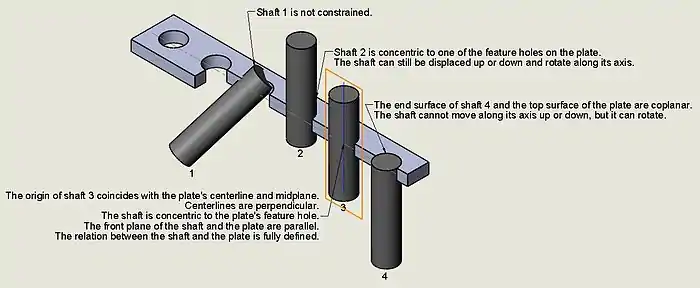
Ideally, a rod will need to be concentric to a hole drilled through the plate where it will be inserted, so the constraint "concentric" guarantees that the diameter of the rod and the diameter of the hole maintain a common centerline, thus "locking" the manner the rod relates to the hole in the plate, this means that the rod could still slide on either direction since the position of its ends has not been limited.

See also
References
Sources
Introducing AutoCAD 2010 and AutoCAD LT 2010 (pages 117-122), by George Omura. 2009; 1st. Edition. Wiley Publishing, Inc., Indianapolis, Indiana. ISBN 978-0-470-43867-1 Hard Cover; 384 pages.
Autodesk® Inventor® 2011 Essentials Plus (pages 312-341), by Daniel T. Banach; Travis Jones; Alan J. Kalameja. 2011; Delmar/Cengage Learning, Autodesk Press. Printed in the United States of America. ISBN 978-1-1111-3527-0; ISBN 1-1111-3527-4. New York.