Hawkins Electrical Guide
The Hawkins Electrical Guide was a technical engineering book written by Nehemiah Hawkins, first published in 1914, intended to explain the highly complex principles of the new technology of electricity in a way that could be understood by the common man. The book is notable for the extremely high number of detailed illustrations it contains, and the small softbound size of the volumes.
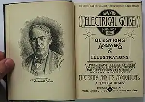
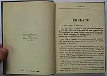

The book was published by Theodore Audel & Company, and the majority of the illustrative content became the basis of decades of follow-up books published under the Audels brand name. The illustrative content of these books can still be found in Audels books sold new today.
Because the Hawkins Electrical Guide was printed in the United States prior to 1923, the content of the books has passed into the public domain.
Free media access on the Internet
Due to several book digitizing initiatives such as the Gutenberg project, and The Hawkins Electrical Guide Online at the Wayback Machine (archived March 21, 2015), many of these older public domain books are becoming available on the Internet. This series of books is currently available for free, non-commercial use from Google Books and each volume can be downloaded as a PDF, though the illustration scan quality is not as good as the ones being added to Wikipedia on this page by Wikipedia contributors.
Google Books Volume Links
As of September 2008, Google Books does not provide a simple, direct means to find each volume of this media set, and appears to include scanned copies of different volumes from different libraries and copyright dates from 1914-1917. Scan quality varies from one volume to the next. For your convenience, links to the available scanned media are provided here:
- Volume 1, Copyright 1917, Impression 1921, from the University of California
- Volume 2, Copyright 1917, from the University of Wisconsin - Madison, General Library System
- Volume 3, Copyright 1917, Impression 1926, from the Harvard College Library
- Volume 4, Copyright 1917, from the University of Wisconsin - Madison, General Library System,
- Volume 5, Copyright 1917, from the University of Wisconsin - Madison, General Library System
- Volume 6, Copyright 1917, from the Harvard College Library
- Volume 7 & 8, Copyright 1914, from the New York Public Library
- Volume 9, Copyright 1917, Impression 1926, from the Harvard College Library
- Volume 10, Copyright 1917, Impression 1924-1925, from the Harvard College Library
Illustrations from Volume 1
Chapter 14: The Dynamo: Current Commutation
 |
 |
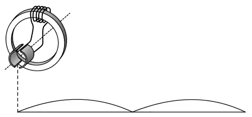
| Page 174, Figure 182 Main Wikipedia article: Gramme machine Description: Separate excitation of an electric generator. DC generator with commutation is shown, but the principle also applies to AC alternators. |
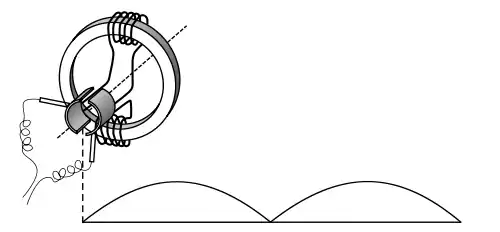
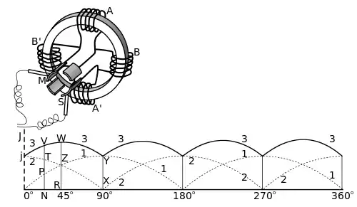
Page 175, Figure 183 Main Wikipedia article: Gramme machine Description: A one pole, two coil Gramme ring. The second coil is wired in series with the first and the voltage of both is added together. |
 |
 |
| Page 177, Figure 185 Main Wikipedia article: Gramme machine Description: A four coil Gramme ring. The coils of A and A' sum together as do the coils of B and B', producing two pulses of power 90 degrees out of phase with each other. When coils A and A' are at maximum output, coils B and B' are at zero output. |
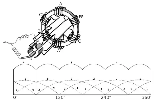
Page 178, Figure 186 Main Wikipedia article: Gramme machine Description: A three pole, six coil Gramme ring, and a graph of the combined three poles, each 120 degrees out of phase from the other and summing together. |
Chapter 15: Classes of Dynamo
 |
 |
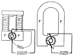
| Page 183 Main Wikipedia article: Excitation (magnetic) Description: A self-excited shunt-wound DC generator is shown on the left, and a magneto DC generator with permanent field magnets is shown on the right. The shunt-wound generator output varies with the current draw, while the magneto output is steady regardless of load variations. |
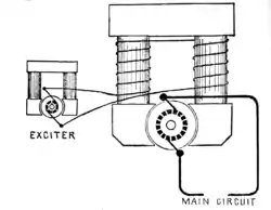
Page 196 Main Wikipedia article: Excitation (magnetic) Description: A separately excited DC generator with bipolar field magnets. Separately excited generators like this are commonly used for large-scale power transmission plants. The smaller generator can be either a magneto with permanent field magnets or another self-excited generator. |
Chapter 16: Field Magnets
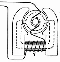 |
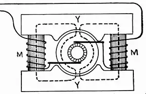 |
| Page 200, Figure 201 Main Wikipedia article: Field coil Description: Salient pole, bipolar field, series-wound DC generator. |
Page 201, Figure 203 Main Wikipedia article: Field coil Description: Consequent pole, bipolar field, series-wound DC generator. |
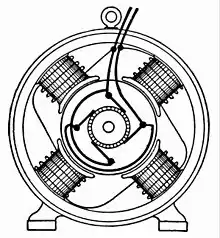 | |
| Page 202, Figure 206 Main Wikipedia article: Field coil Description: Consequent pole, four-field, shunt-wound DC generator |
Chapter 17: The Armature
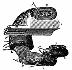 |
 |
| Page 223 Main Wikipedia article: Gramme machine Description: Early form of the Gramme ring armature with coils penetrating the interior of the ring. |
Page 224 Main Wikipedia article: Gramme machine Description: Modern design of the Gramme ring, wrapped only around the exterior of the core. |
 |
 |
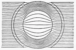
| Page 225 Main Wikipedia article: Gramme machine Description: Diagram of magnetic lines through a Gramme ring, showing the very few magnetic lines of force crossing the center gap. |
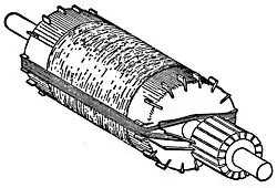
Page 226 Main Wikipedia article: Gramme machine Description: Example of a single winding around the exterior of a drum core with no wires penetrating the interior. |
Chapter 19: Theory of the Armature
 |
 |
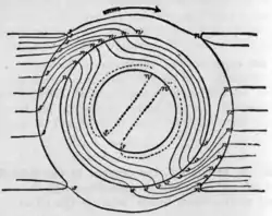
| Page 264 Main Wikipedia article: Commutator (electric) Description: Exaggerated example of how the field is distorted by the rotor. |
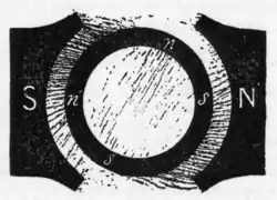
Page 265 Main Wikipedia article: Commutator (electric) Description: Iron filings show the distorted field across the rotor. |
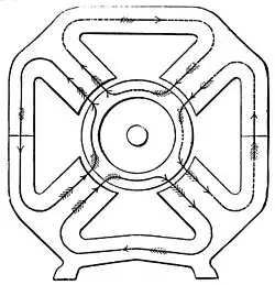 | |
| Page 281 Main Wikipedia article: Field coil Description: Field lines of a four-pole stator passing through a Gramme ring or drum rotor. |
Chapter 20: Commutation and the Commutator
 |
 |
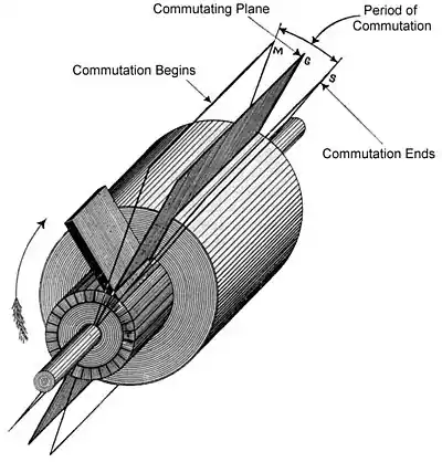
| Page 284 Main Wikipedia article: Commutator (electric) Description: In a dynamo, the contact point of where a pair of brushes touch the commutator is referred to as the commutating plane. In this diagram the commutating plane is shown for just one of the brushes. |
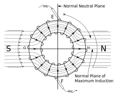
Page 285 Main Wikipedia article: Commutator (electric) Description: Centered position of the commutating plane if there were no field distortion effects. |
 |
 |
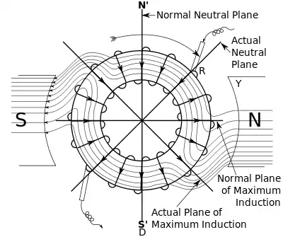
| Page 286 Main Wikipedia article: Commutator (electric) Description: Actual position of the commutating plane to compensate for field distortion. |
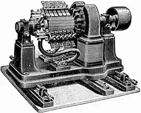
Page 301, Figure 328 Main Wikipedia article: Electrical generator Description: Dynamos are no longer used for power generation due to the size and complexity of the commutator needed for high power applications. This large belt-driven high-current dynamo produced 310 amperes at 7 volts, or 2,170 watts, when spinning at 1400 RPM. |
Illustrations from Volume 2
Chapter 35: Operation of Motors
 |
|
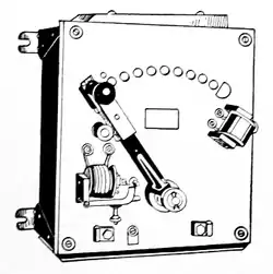
| Page 669 Main article: Brushed DC electric motor Description: 1917 DC motor manual starting rheostat, with no-voltage and overload release features. |
Illustrations from Volume 4
Chapter 46: Alternating Currents
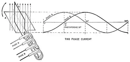 |
| Page 669, Figure 1253 Main article: Two-phase electric power Description: A simplified diagram of a two-phase alternator |
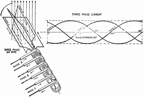 |
| Page 1026, Figure 1260 Main article: Three-phase electric power Elementary six-wire three-phase alternator, with each phase using a separate pair of transmission wires. |
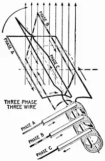 |
| Page 1026, Figure 1261 Main article: Three-phase electric power Description: Elementary three-wire three-phase alternator, showing how the phases can share only three transmission wires |
Illustrations from Volume 6
Chapter 68: Wave Form Measurement
 |
 |
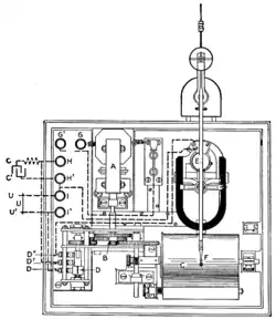
| Page 1850, Figure 2957 Main article: Oscilloscope Description: Diagram of Hospitalier Ondograph |
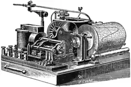
Page 1851, Figure 2958 Main article: Oscilloscope Description: View of Hospitalier Ondograph |
 |
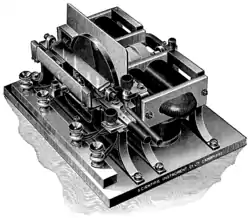 |
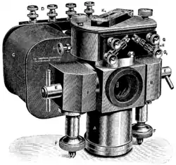
| Page 1858, Figure 2607 Main article: Oscilloscope Description: Duddell Moving Coil Oscilliograph |
Page 1865, Figure 2620 Main article: Oscilloscope Description: Time-index marking generator for use with Duddell moving-coil oscillograph |
 |
 |
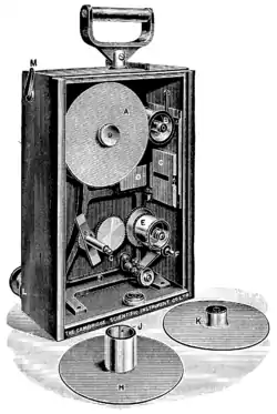
| Page 1866, Figure 2621, 2622, 2623 Main article: Oscilloscope Description: Interior of cinematograph camera as used on Duddell moving coil oscillograph for obtaining long records. |
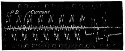
Page 1867, Figure 2625 Main article: Oscilloscope Description: Oscilliograph recorded on moving film showing sparking as a high-voltage switch is opened |
Illustrations from Volume 7
Chapter 66, Power Stations
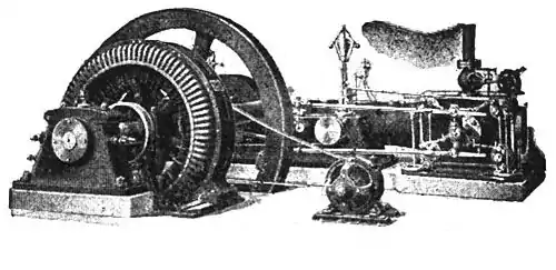 |
| Page 1979 Main article: Electric generator Description: A 50,000 - 100,000 KVA direct-driven power station AC alternator with a separate belt-driven exciter generator. |
Notes, References
- The author's full name was Nehemiah Hawkins. Cf: Joule's Experiment. DOB 1833.
- In 1882 a Mr. N. Hawkins "writing under the name Theodore Audel" founded a magazine called "Steam". Platt's History. Another Hawkins pseudonym: William Rogers.
- Also available online: Hawkins, Nehemiah. "Maxims and instructions for the boiler room."(1903) - Internet Archive
- Hawkins bibliography at Open Library
- Historical advertisement for the Hawkins Electrical Guide, Popular Science monthly, February 1919, Page 6, Scanned by Google Books: https://books.google.com/books?id=7igDAAAAMBAJ&pg=PA6