Parallel axis theorem
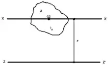
Parallel axis theorem state that "The Moment of Inertia (M I) about any axis in the plane of lamina is equal to the sum of the M.I of that lamina about the centoidal axis parallel to the given axis and the product of the area of lamina and square of the perpendicular distance between the two axis"
PERPENDICULAR AXIS THEOREM FORMULA
I(a×b)=Ig+A(h)2
Mass moment of inertia

Suppose a body of mass m is rotated about an axis z passing through the body's center of mass. The body has a moment of inertia Icm with respect to this axis. The parallel axis theorem states that if the body is made to rotate instead about a new axis z′, which is parallel to the first axis and displaced from it by a distance d, then the moment of inertia I with respect to the new axis is related to Icm by
Explicitly, d is the perpendicular distance between the axes z and z′.
The parallel axis theorem can be applied with the stretch rule and perpendicular axis theorem to find moments of inertia for a variety of shapes.

Derivation
We may assume, without loss of generality, that in a Cartesian coordinate system the perpendicular distance between the axes lies along the x-axis and that the center of mass lies at the origin. The moment of inertia relative to the z-axis is
The moment of inertia relative to the axis z′, which is a perpendicular distance D along the x-axis from the centre of mass, is
Expanding the brackets yields
The first term is Icm and the second term becomes mD2. The integral in the final term is a multiple of the x-coordinate of the center of mass – which is zero since the center of mass lies at the origin. So, the equation becomes:
Tensor generalization
The parallel axis theorem can be generalized to calculations involving the inertia tensor. Let Iij denote the inertia tensor of a body as calculated at the centre of mass. Then the inertia tensor Jij as calculated relative to a new point is
where is the displacement vector from the centre of mass to the new point, and δij is the Kronecker delta.
For diagonal elements (when i = j), displacements perpendicular to the axis of rotation results in the above simplified version of the parallel axis theorem.
The generalized version of the parallel axis theorem can be expressed in the form of coordinate-free notation as
where E3 is the 3 × 3 identity matrix and is the outer product.
Further generalization of the parallel axis theorem gives the inertia tensor about any set of orthogonal axes parallel to the reference set of axes x, y and z, associated with the reference inertia tensor, whether or not they pass through the center of mass.[1]
Second moment of area
The parallel axes rule also applies to the second moment of area (area moment of inertia) for a plane region D:
where Iz is the area moment of inertia of D relative to the parallel axis, Ix is the area moment of inertia of D relative to its centroid, A is the area of the plane region D, and r is the distance from the new axis z to the centroid of the plane region D. The centroid of D coincides with the centre of gravity of a physical plate with the same shape that has uniform density.
Polar moment of inertia for planar dynamics

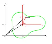
The mass properties of a rigid body that is constrained to move parallel to a plane are defined by its center of mass R = (x, y) in this plane, and its polar moment of inertia IR around an axis through R that is perpendicular to the plane. The parallel axis theorem provides a convenient relationship between the moment of inertia IS around an arbitrary point S and the moment of inertia IR about the center of mass R.
Recall that the center of mass R has the property
where r is integrated over the volume V of the body. The polar moment of inertia of a body undergoing planar movement can be computed relative to any reference point S,
where S is constant and r is integrated over the volume V.
In order to obtain the moment of inertia IS in terms of the moment of inertia IR, introduce the vector d from S to the center of mass R,
The first term is the moment of inertia IR, the second term is zero by definition of the center of mass, and the last term is the total mass of the body times the square magnitude of the vector d. Thus,
which is known as the parallel axis theorem.[2]
Moment of inertia matrix
The inertia matrix of a rigid system of particles depends on the choice of the reference point.[3] There is a useful relationship between the inertia matrix relative to the center of mass R and the inertia matrix relative to another point S. This relationship is called the parallel axis theorem.
Consider the inertia matrix [IS] obtained for a rigid system of particles measured relative to a reference point S, given by
where ri defines the position of particle Pi, i = 1, ..., n. Recall that [ri − S] is the skew-symmetric matrix that performs the cross product,
for an arbitrary vector y.
Let R be the center of mass of the rigid system, then
where d is the vector from the reference point S to the center of mass R. Use this equation to compute the inertia matrix,
Expand this equation to obtain
The first term is the inertia matrix [IR] relative to the center of mass. The second and third terms are zero by definition of the center of mass R,
And the last term is the total mass of the system multiplied by the square of the skew-symmetric matrix [d] constructed from d.
The result is the parallel axis theorem,
where d is the vector from the reference point S to the center of mass R.[3]
Identities for a skew-symmetric matrix
In order to compare formulations of the parallel axis theorem using skew-symmetric matrices and the tensor formulation, the following identities are useful.
Let [R] be the skew symmetric matrix associated with the position vector R = (x, y, z), then the product in the inertia matrix becomes
This product can be computed using the matrix formed by the outer product [R RT] using the identify
where [E3] is the 3 × 3 identity matrix.
Also notice, that
where tr denotes the sum of the diagonal elements of the outer product matrix, known as its trace.
See also
References
- A. R. Abdulghany, American Journal of Physics 85, 791 (2017); doi: https://dx.doi.org/10.1119/1.4994835 .
- Paul, Burton (1979), Kinematics and Dynamics of Planar Machinery, Prentice Hall, ISBN 978-0-13-516062-6
- T. R. Kane and D. A. Levinson, Dynamics, Theory and Applications, McGraw-Hill, NY, 2005.
External links
| Wikimedia Commons has media related to Steiner's parallel axis theorem. |