Platform chassis
A platform chassis is a form of automobile chassis constructed as a flat plate or platform.
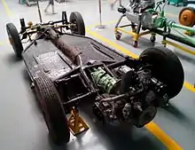
Design
A platform chassis is a separate chassis for a car or small vehicle. It is distinguished from other forms of chassis by being arranged as largely a single flat steel sheet, usually with additional box section stiffeners.[1]
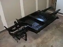
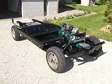
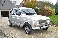
Platform chassis developed after the ladder chassis or cruciform chassis designs in the 1930s, once car bodies began to be pressed from large steel sheets, rather than the chassis assembled from rolled channel sections. As a semi-monocoque they are still a form of body-on-frame construction, rather than a monocoque or unibody where the bodyshell and chassis are integrated into one component. Although both body and platform chassis are each made from similar pressed steel panels welded together, they were often bolted as the final two units and so may still be separable after construction.
Achieving sufficient rigidity is difficult with a pure platform and so they are usually extended vertically with some form of box or tube section. This can be either a perimeter frame (e.g. Renault 4) or a central spine (e.g. VW Beetle). Longitudinal rigidity is more critical than transverse rigidity and so this stiffening is mostly as front to back girders, rather than crosswise. The diaphragm sheet is usually pressed into shallow stiffening ridges as well, but these are mostly to stop drumming noise and are too minor to provide major structural strength.
Platforms are usually the full width of the car, but shorter and only span the length between the wheels. Suspension attachments for the wheels and the weight of the engine and transmission are carried on additional subframes beyond this. These subframes may be formed of box section tubes welded on to the chassis, deep-drawn box sections formed from sheet, or as separate subframes that are bolted in place.
Platform chassis have been used for both rear-wheel drive (Beetle) and front-wheel drive (Renault) layouts. However they keep the engine at the driven end, with a transaxle, rather than using the propeller shaft of the Hotchkiss layout of front-engine, rear-drive that was universal with chassis designs beforehand. This avoided transmitting the propeller shaft torque through the platform. Where a propeller shaft has been used, these have been for rare examples with four-wheel drive.
Attaching the suspension to a platform chassis requires independent suspension and encourages the use of suspension features such as torsion bars or trailing arms. As the chassis is in a single plane, it would be difficult to use a solid axle, without raising the entire platform above the axle line. It is also difficult to arrange spring attachments for springs such as half-elliptic springs requiring distance fore and aft of the axle line, or for coil spring or strut suspensions needing an attachment point raised vertically above the platform. Instead, springs such as torsion bars are used. Whether these are transverse or longitudinal, they lie in the horizontal plane of the platform and so can be worked in to such a chassis. Other torsion-based systems, such as twist-beam rear suspension, may be used as well for front-wheel drive cars with light rears.
Volkswagen Beetle chassis
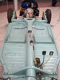
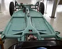
The Volkswagen Type 1 Beetle used a platform chassis, with independent torsion bar suspension at each end. The 'Volkswagen', 'Peoples' Car' or 'KdF-Wagen' project began in 1933 and by 1934 Porsche had sketched out a design for a rear-engined, platform chassis car with four seats and torsion bar suspension.[2] A central stiffening tube provided much of the strength of the chassis.
This basic design proceeded through the pre-war Porsche Type 60, and several wartime military vehicles, before finally the first post-war mass-production Volkswagen Beetles of 1945.[3]
WWII military vehicles
In 1936, Porsche adapted the developing KdF-Wagen 'domestic' car as a sporting car suitable for the auto trials organised by the NSKK. These were slow-speed competitions across off-road terrain and obstacles, which developed both driving skill and vehicle agility, in ways which were expected to be useful for military motoring. This Porsche Type 62 was an open-topped, open-sided four seater, still with rounded bodywork. Although it performed well in military trials at Münsingen, its appearance was considered to be 'too civilian'.[4]
Porsche continued to develop the Type 62 with such features as a rear portal axle to give increased ground clearance and the ability to move with infantry at a walking pace. The rounded bodywork was also replaced with ribbed flat panels, with doors,[lower-roman 1] and by the end of 1939 this had been accepted as the military Type 82 Kübelwagen.[6] The Kübelwagen was highly effective, in large part due to the light weight achieved by use of its platform chassis. It weighed only 1,510 lb, the same design weight as the road car, and was 200-300 lb lighter than its rival vehicles from Opel, DKW and Adler.[7]
A four-wheel drive version was also developed, again using the same platform chassis and basic layout, but under the civilian enclosed bodywork. This became the Type 87 Kommandeurswagen (Porsche Type 287) and was intended for use by senior field commanders. The central tube of the chassis pan was enlarged to give space for a propeller shaft and a powered front axle provided, with similar driveshafts as the rear axle.[7]
VW Beetle
The Beetle powertrain comprised a rear-mounted flat-four engine with a longitudinal transaxle ahead of it. The rear suspension was by swing axles. The first 1945 civilian Beetle used a platform chassis which stopped short of the rear wheels and which had a central stiffening tube. This tube extended rearwards as a Y-shaped fork, which passed each side of the transaxle and to the engine mounts. The rear swing axles were also held at their outboard ends by flat plate trailing arms, which were pivoted on the ends of a crosswise tube, containing the torsion bars. At this time the rear shock absorbers were only single-acting, lever-type.[8]
The front suspension was provided by pairs of short trailing arms, again with transverse torsion bars mounted in two separate tubes, mounted ahead of the flat platform.[9] These torsion bars were stacks of flat strips, and the number of leaves was changed to vary the suspension stiffness, over the production of the Beetle.[10]
An advantage for the production of the vehicle was that controls such as the driver's pedals and brake piping, the gear stick and the handbrake which required connections to the engine or drive train could be installed onto the platform before the body was added. Even, until 1952,[11] the engine choke control and its Bowden cable were mounted on the central tunnel. Unlike most contemporary chassis-on-frame designs though, the steering column was mounted on the bodyshell and was not connected to the steering box on the chassis platform until the two were joined.
In the 35 year production history of the Beetle, the basic platform chassis remained largely unchanged, except for one change to the front suspension of the 'Super Beetle'.
Developments
From 1970, the new 1302 'Super Beetle' adopted MacPherson strut front suspension.[12] This increased front luggage capacity by nearly 50%, also due to a slightly lengthened front bonnet, but the upper mounts of the struts now coupled suspension forces into the inner wing panels of bodyshell rather than the platform: the chassis was now no longer a pure platform. The 1303 'Super Beetle' continued in production until 1975, although the Economy Beetle continued in parallel with it, still using the trailing arms and platform chassis.[13]
Beetle conversions
.jpg.webp)
The platform chassis, and the large number of available VW Beetles, encouraged the use of the Beetle platform as a donor car for building kit cars. The most iconic of these was the dune buggy: a stripped-down Beetle chassis, with the simplest fibreglass 'bathtub' body on top of this.
The first production dune buggy, the Meyers Manx, used a shortened VW platform as a basis. The front of the chassis was cut off and replaced by a taller structure of welded square steel tube. This made the front end vertically stiffer and the suspension was replaced by one based on Chevrolet parts, although still with double trailing arms. The Meyers Manx was widely copied and most of these copies retained the full VW platform and VW front suspension.
Safety
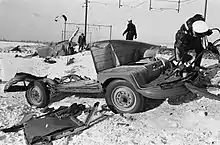
Platform chassis were not significantly more or less safe than contemporary ladder chassis, although much less safe in an impact than a modern design with a monocoque integrated into a passenger safety cell. They had a tendency in serious accidents for the complete bodyshell to separate from the chassis, as did the ladder chassis. However with the platform chassis, this formed the floor of the passenger area, rather than the body tub, and had the seats mounted to it. The passengers could thus stay with their seats on the chassis, while the bodyshell tried to pass through them.
Modern platform chassis

Modern developments of chassis materials, bodyshells materials and design, and also changes in drivetrain have given the platform chassis a resurgence. They are now in use for some electric and hybrid cars, such as the Tesla S.
An electric drivetrain (either hybrid or pure battery) does not require mechanical stiffness between an engine and final drive. The entire drivetrain can be mounted in a subframe at one, or increasingly both, ends.
Battery storage is required, and as the battery pack is heavy it is an advantage for stability to mount it in the largest flat layer, as low down as possible. The pack weight for a Tesla S is 1,200 pounds (540 kg)[14] As these are composed of 7,104 cells, packaged into 16 modules,[15] their overall shape is flexible and can be adjusted to best fit the vehicle. This makes the platform chassis a good way to carry it, with the batteries themselves either above or below the chassis platform, making them easier to access for exchange.[lower-roman 2]
Punt chassis
.jpg.webp)
A punt chassis is similar to the platform chassis, but in addition to the lower platform there are also deep raised sides. These give vertical stiffness, without requiring added stiffeners.
Punt chassis have often been used with armoured vehicles. The armoured outer bodyshell forms a robust monocoque which can serve double duty as the vehicle's chassis. Such armoured vehicles require all-wheel drive for off-road capacity with their weight, which many involve six or eight wheels, and so have often used a H-drive layout for the drivetrain. Rather than axles connected by a central propeller shaft, the two sides are linked fore-and-aft by driveshafts in the lower corners of the punt. This also allows greater useful space inside for crew or equipment.[16][17]
References
| Wikimedia Commons has media related to Platform chassis. |
- Kübelwagen is a contraction of Kübelsitzwagen, meaning "bucket-seat car" because German light military cars since 1923 and a body style developed by Karosseriefabrik Nikolaus Trutz, had used open-sided bodies without doors, allowing a rapid exit, and so were fitted with bucket seats to prevent passengers from falling out.[5]
- In the Tesla's case, the batteries are protected from impact by a further steel 'armour plate' beneath them.[15]
- Setright, Anatomy of the Motor Car (1976), pp. 182–185
- Ludvigsen, Professor Porsche's Wars (2014), pp. 113–117.
- Ludvigsen, Professor Porsche's Wars (2014), pp. 117–123.
- Ludvigsen, Professor Porsche's Wars (2014), pp. 132–134.
- Ludvigsen, Professor Porsche's Wars (2014), pp. 78,116,132,136.
- Ludvigsen, Professor Porsche's Wars (2014), pp. 135–136.
- Ludvigsen, Professor Porsche's Wars (2014), pp. 136–137.
- Etzold (1988), pp. 8–9.
- Etzold (1988), pp. 15–17.
- Etzold (1988), p. 17.
- Etzold (1988), pp. 29,33.
- Etzold (1988), pp. 138,178.
- Etzold (1988), p. 178.
- Roper, L. David. "Tesla Model S Data". Retrieved 2015-04-05.
- Musk, Elon (2013-10-04). "Model S Fire". Tesla Motors.
- Munro (2002), pp. 70–75
- Ware (1994)
- Etzold, H.R. (1988). Beetle: the definitive history. Vol 1. Haynes. ISBN 0-85429-647-6.CS1 maint: ref=harv (link)
- Ludvigsen, Karl (2014). Professor Porsche's Wars. Pen & Sword Military. ISBN 978-1-52672-679-7.
- Munro, Bill (2002). Alvis Saracen Family. Crowood Press. ISBN 1-86126-537-9.CS1 maint: ref=harv (link)
- Setright, L. J. K. (1976). "Chassis". In Ian Ward (ed.). Anatomy of the Motor Car. Orbis. ISBN 0 85613 230 6.
- Ware, Pat (1994). In National Service. Warehouse Publications. ISBN 0-9525563-0-8.CS1 maint: ref=harv (link)