Real-time Control System
Real-time Control System (RCS) is a reference model architecture, suitable for many software-intensive, real-time computing control problem domains. It defines the types of functions needed in a real-time intelligent control system, and how these functions relate to each other.
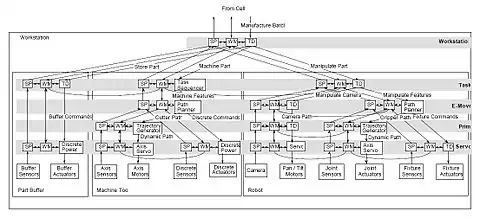
RCS is not a system design, nor is it a specification of how to implement specific systems. RCS prescribes a hierarchical control model based on a set of well-founded engineering principles to organize system complexity. All the control nodes at all levels share a generic node model.[1]
Also RCS provides a comprehensive methodology for designing, engineering, integrating, and testing control systems. Architects iteratively partition system tasks and information into finer, finite subsets that are controllable and efficient. RCS focuses on intelligent control that adapts to uncertain and unstructured operating environments. The key concerns are sensing, perception, knowledge, costs, learning, planning, and execution.[1]
Overview
A reference model architecture is a canonical form, not a system design specification. The RCS reference model architecture combines real-time motion planning and control with high level task planning, problem solving, world modeling, recursive state estimation, tactile and visual image processing, and acoustic signature analysis. In fact, the evolution of the RCS concept has been driven by an effort to include the best properties and capabilities of most, if not all, the intelligent control systems currently known in the literature, from subsumption to SOAR, from blackboards to object-oriented programming.[2]
RCS (real-time control system) is developed into an intelligent agent architecture designed to enable any level of intelligent behavior, up to and including human levels of performance. RCS was inspired by a theoretical model of the cerebellum, the portion of the brain responsible for fine motor coordination and control of conscious motions. It was originally designed for sensory-interactive goal-directed control of laboratory manipulators. Over three decades, it has evolved into a real-time control architecture for intelligent machine tools, factory automation systems, and intelligent autonomous vehicles.[3]
RCS applies to many problem domains including manufacturing examples and vehicle systems examples. Systems based on the RCS architecture have been designed and implemented to varying degrees for a wide variety of applications that include loading and unloading of parts and tools in machine tools, controlling machining workstations, performing robotic deburring and chamfering, and controlling space station telerobots, multiple autonomous undersea vehicles, unmanned land vehicles, coal mining automation systems, postal service mail handling systems, and submarine operational automation systems.[2]
History
RCS has evolved through a variety of versions over a number of years as understanding of the complexity and sophistication of intelligent behavior has increased. The first implementation was designed for sensory-interactive robotics by Barbera in the mid 1970s.[4]
RCS-1
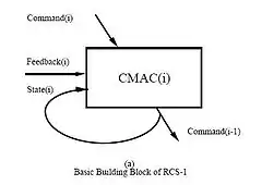
In RCS-1, the emphasis was on combining commands with sensory feedback so as to compute the proper response to every combination of goals and states. The application was to control a robot arm with a structured light vision system in visual pursuit tasks. RCS-1 was heavily influenced by biological models such as the Marr-Albus model,[5] and the Cerebellar Model Arithmetic Computer (CMAC).[6] of the cerebellum.[2]
CMAC becomes a state machine when some of its outputs are fed directly back to the input, so RCS-1 was implemented as a set of state-machines arranged in a hierarchy of control levels. At each level, the input command effectively selects a behavior that is driven by feedback in stimulus-response fashion. CMAC thus became the reference model building block of RCS-1, as shown in the figure.
A hierarchy of these building blocks was used to implement a hierarchy of behaviors such as observed by Tinbergen[7] and others. RCS-1 is similar in many respects to Brooks' subsumption architecture,[8] except that RCS selects behaviors before the fact through goals expressed in commands, rather than after the fact through subsumption.[2]
RCS-2
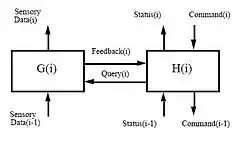
The next generation, RCS-2, was developed by Barbera, Fitzgerald, Kent, and others for manufacturing control in the NIST Automated Manufacturing Research Facility (AMRF) during the early 1980s.[9][10][11] The basic building block of RCS-2 is shown in the figure.
The H function remained a finite state machine state-table executor. The new feature of RCS-2 was the inclusion of the G function consisting of a number of sensory processing algorithms including structured light and blob analysis algorithms. RCS-2 was used to define an eight level hierarchy consisting of Servo, Coordinate Transform, E-Move, Task, Workstation, Cell, Shop, and Facility levels of control.
Only the first six levels were actually built. Two of the AMRF workstations fully implemented five levels of RCS-2. The control system for the Army Field Material Handling Robot (FMR)[12] was also implemented in RCS-2, as was the Army TMAP semi-autonomous land vehicle project.[2]
RCS-3
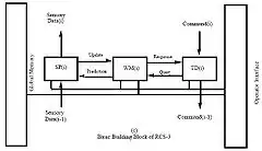
RCS-3 was designed for the NBS/DARPA Multiple Autonomous Undersea Vehicle (MAUV) project[13] and was adapted for the NASA/NBS Standard Reference Model Telerobot Control System Architecture (NASREM) developed for the space station Flight Telerobotic Servicer[14] The basic building block of RCS-3 is shown in the figure.
The principal new features introduced in RCS-3 are the World Model and the operator interface. The inclusion of the World Model provides the basis for task planning and for model-based sensory processing. This led to refinement of the task decomposition (TD) modules so that each have a job assigner, and planner and executor for each of the subsystems assigned a job. This corresponds roughly to Saridis'[15] three level control hierarchy.[2]
RCS-4
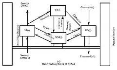
RCS-4 is developed since the 1990s by the NIST Robot Systems Division. The basic building block is shown in the figure). The principal new feature in RCS-4 is the explicit representation of the Value Judgment (VJ) system. VJ modules provide to the RCS-4 control system the type of functions provided to the biological brain by the limbic system. The VJ modules contain processes that compute cost, benefit, and risk of planned actions, and that place value on objects, materials, territory, situations, events, and outcomes. Value state-variables define what goals are important and what objects or regions should be attended to, attacked, defended, assisted, or otherwise acted upon. Value judgments, or evaluation functions, are an essential part of any form of planning or learning. The application of value judgments to intelligent control systems has been addressed by George Pugh.[16] The structure and function of VJ modules are developed more completely developed in Albus (1991).[2][17]
RCS-4 also uses the term behavior generation (BG) in place of the RCS-3 term task 5 decomposition (TD). The purpose of this change is to emphasize the degree of autonomous decision making. RCS-4 is designed to address highly autonomous applications in unstructured environments where high bandwidth communications are impossible, such as unmanned vehicles operating on the battlefield, deep undersea, or on distant planets. These applications require autonomous value judgments and sophisticated real-time perceptual capabilities. RCS-3 will continue to be used for less demanding applications, such as manufacturing, construction, or telerobotics for near-space, or shallow undersea operations, where environments are more structured and communication bandwidth to a human interface is less restricted. In these applications, value judgments are often represented implicitly in task planning processes, or in human operator input.[2]
Methodology
In the figure, an example of the RCS methodology for designing a control system for autonomous onroad driving under everyday traffic conditions is summarized in six steps.[18]
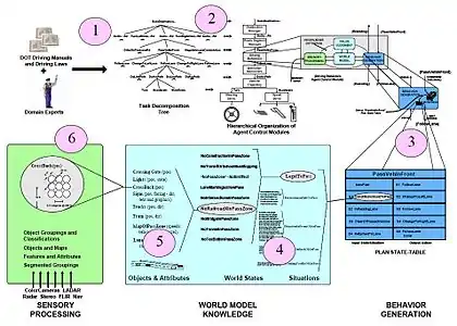
- Step 1 consists of an intensive analysis of domain knowledge from training manuals and subject matter experts. Scenarios are developed and analyzed for each task and subtask. The result of this step is a structuring of procedural knowledge into a task decomposition tree with simpler and simpler tasks at each echelon. At each echelon, a vocabulary of commands (action verbs with goal states, parameters, and constraints) is defined to evoke task behavior at each echelon.[18]
- Step 2 defines a hierarchical structure of organizational units that will execute the commands defined in step 1. For each unit, its duties and responsibilities in response to each command are specified. This is analogous to establishing a work breakdown structure for a development project, or defining an organizational chart for a business or military operation.[18]
- Step 3 specifies the processing that is triggered within each unit upon receipt of an input command. For each input command, a state-graph (or statetable or extended finite state automaton) is defined that provides a plan (or procedure for making a plan) for accomplishing the commanded task. The input command selects (or causes to be generated) an appropriate state-table, the execution of which generates a series of output commands to units at the next lower echelon. The library of state-tables contains a set of statesensitive procedural rules that identify all the task branching conditions and specify the corresponding state transition and output command parameters.[18]
The result of step 3 is that each organizational unit has for each input command a state-table of ordered production rules, each suitable for execution by an extended finite state automaton (FSA). The sequence of output subcommands required to accomplish the input command is generated by situations (i.e., branching conditions) that cause the FSA to transition from one output subcommand to the next.[18]
- In step 4, each of the situations that are defined in step 3 are analyzed to reveal their dependencies on world and task states. This step identifies the detailed relationships between entities, events, and states of the world that cause a particular situation to be true.[18]
- In step 5, we identify and name all of the objects and entities together with their particular features and attributes that are relevant to detecting the above world states and situations.[18]
- In step 6, we use the context of the particular task activities to establish the distances and, therefore, the resolutions at which the relevant objects and entities must be measured and recognized by the sensory processing component. This establishes a set of requirements and/or specifications for the sensor system to support each subtask activity.[18]
Software

Based on the RCS Reference Model Architecture the NIST has developed a Real-time Control System Software Library. This is an archive of free C++, Java and Ada code, scripts, tools, makefiles, and documentation developed to aid programmers of software to be used in real-time control systems, especially those using the Reference Model Architecture for Intelligent Systems Design.[19]
Applications
- The ISAM Framework is an RCS application to the Manufacturing Domain.
- The 4D-RCS Reference Model Architecture is the RCS application to the Vehicle Domain, and
- The NASA/NBS Standard Reference Model for Telerobot Control Systems Architecture (NASREM) is an application to the Space Domain.
References
- NIST ISD Research areas overview. Last Updated: 5/12/2003. Accessed Aug 2, 2009.
- James S. Albus (1992). A Reference Model Architecture for Intelligent Systems Design Archived 2008-09-16 at the Wayback Machine Intelligent Systems Division, Manufacturing Engineering Laboratory, National Institute of Standards and Technology.
- Jim Albus, Tony Barbera, Craig Schlenoff (2004). "RCS: An Intelligent Agent Architecture" In: Proc. of 2004 AAAI Conference: Workshop on Intelligent Agent Architectures: Combining the Strengths of Software Engineering & Cognitive Systems, San Jose, CA.
- A.J. Barbera, J.S. Albus, M.L. Fitzgerald (1979). "Hierarchical Control of Robots Using Microcomputers". In: Proceedings of the 9th International Symposium on Industrial Robots, Washington, DC, March 1979.
- J.S. Albus (1971). "A Theory of Cerebellar Function". In: Mathematical Biosciences, Vol. 10, pgs. 25–61, 1971
- J.S. Albus (1975). "A New Approach to Manipulator Control : The Cerebellar Model Articulation Controller (CMAC)". In: Transactions ASME, September 1975.
- Nico Tinbergen (1951). The Study of Instinct. Clarendon, Oxford.
- Rodney Brooks (1986). "A Robust Layered Control System for a Mobile Robot". In: IEEE Journal of Robotics and Automation. Vol. RA-2, [1], March, 1986.
- J.A. Simpson, R.J. Hocken, J.S. Albus (1983). "The Automated Manufacturing Research Facility of the National Bureau of Standards". In: Journal of Manufacturing Systems, Vol. 1, No. 1, 1983.
- J.S. Albus, C. McLean, A.J. Barbera, M.L. Fitzgerald (1982). "An Architecture for Real-Time Sensory-Interactive Control of Robots in a Manufacturing Environment". In: 4th IFAC/IFIP Symposium on Information Control Problems in Manufacturing Technology. Gaithersburg, MD, October 1982
- E. W. Kent, J.S. Albus (1984). "Servoed World Models as Interfaces Between Robot Control Systems and Sensory Data". In: Robotica, Vol. 2, No.1, January 1984.
- H.G. McCain, R.D. Kilmer, S. Szabo, A. Abrishamian (1986). "A Hierarchically Controlled Autonomous Robot for Heavy Payload Military Field Applications". In: Proceedings of the International Conference on Intelligent Autonomous Systems. Amsterdam, The Netherlands, December 8–11, 1986.
- J.S. Albus (1988). System Description and Design Architecture for Multiple Autonomous Undersea Vehicles. National Institute of Standards and Technology, Technical Report 37 1251, Gaithersburg, MD, September 1988.
- J.S. Albus, H.G. McCain, R. Lumia (1989). NASA/NBS Standard Reference Model for Telerobot Control System Architecture (NASREM). National Institute of Standards and Technology, Technical Report 1235, Gaithersburg, MD, April 1989.
- George N. Saridis (1985). Foundations of the Theory of Intelligent Controls. IEEE Workshop on Intelligent Control, 1985
- G.E. Pugh, G.L. Lucas, (1980). Applications of Value-Driven Decision Theory to the Control and Coordination of Advanced Tactical Air Control Systems. Decision-Science Applications, Inc., Report No. 218, April 1980
- J.S. Albus (1991). "Outline for a Theory of Intelligence". In: IEEE Trans. on Systems, Man, and Cybernetics. Vol. 21, No. 3, May/June 1991.
- James S. Albus & Anthony J. Barbera (2005). RCS: A Cognitive Architecture for Intelligent Multi-Agent Systems. National Institute of Standards and Technology, Gaithersburg, Maryland 20899
- Real-Time Control Systems Library –– Software and Documentation at nist.gov. Accessed Aug 4, 2009.
 This article incorporates public domain material from the National Institute of Standards and Technology website https://www.nist.gov.
External links
| Wikimedia Commons has media related to RCS Reference Model Architecture. |
- RCS The Real-time Control Systems Architecture NIST Homepage