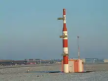
Instrument landing system glide path
Instrument landing system glide path, commonly referred to as a glide path (G/P) or glide slope (G/S), is "a system of vertical guidance embodied in the instrument landing system which indicates the vertical deviation of the aircraft from its optimum path of descent", according to Article 1.106 of the ITU Radio Regulations (ITU RR).[1]


Principle of operation
A glide slope station uses an antenna array sited to one side of the runway touchdown zone. The GS signal is transmitted on a carrier signal using a technique similar to that for the localizer. The centre of the glide slope signal is arranged to define a glide path of approximately 3° above horizontal (ground level). The beam is 1.4° deep (0.7° below the glide-path centre and 0.7° above).
The pilot (or the autopilot, if using autoland) controls the aircraft so that the glide slope indicator remains centered on the display to ensure the aircraft is following the glide path to remain above obstructions and reach the runway at the proper touchdown point (i.e., it provides vertical guidance).
Carrier frequency pairings
Localizer (LOC) and glide slope (G/S) carrier frequencies are paired so that the navigation radio automatically tunes the G/S frequency which corresponds to the selected LOC frequency. The LOC signal is in the 110 MHz range while the G/S signal is in the 330 MHz range.[2]
LOC carrier frequencies range between 108.10 MHz and 111.95 MHz (with the 100 kHz first decimal digit always odd, so 108.10, 108.15, 108.30, etc., are LOC frequencies and are not used for any other purpose).
Two signals are transmitted on one of 40 ILS channels. One is modulated at 90 Hz, the other at 150 Hz. These are transmitted from co-located antennas. Each antenna transmits a narrow beam.
See also
References
- ITU Radio Regulations, Section IV. Radio Stations and Systems – Article 1.106, definition: instrument landing system (ILS)
- "Frequency Allotments" (PDF). NTIA.DOC.gov. January 2008. Retrieved 28 September 2010.