Sarfus
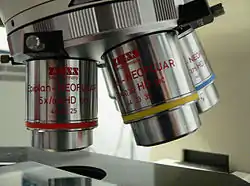
Sarfus is an optical quantitative imaging technique based on the association of:
- an upright or inverted optical microscope in crossed polarization configuration and
- specific supporting plates – called surfs – on which the sample to observe is deposited.
Sarfus visualization is based on the perfect control of the reflection properties of polarized light on a surface, which leads to an increase in the axial sensitivity of optical microscope by a factor of around 100 without reducing its lateral resolution. Thus this new technique increases the sensitivity of standard optical microscope to a point that it becomes possible to directly visualize thin films (down to 0.3 micrometer) and isolated nano-objects in real-time, be it in air or in water.
Principles


A recent study on polarized light coherence leads to the development of new supports – the surfs – having contrast amplification properties for standard optical microscopy in cross polarizers mode.[1] Made of optical layers on an opaque or transparent substrate, these supports do not modify the light polarization after reflection even if the numerical aperture of the incident source is important. This property is modified when a sample is present on a surf, a non-null light component is then detected after the analyzer rendering the sample visible.
The performances of these supports are estimated from the measurement of the contrast (C) of the sample defines by: C = (I1-I0)/(I0+I1) where I0 and I1 represent the intensities reflected by the bare surf and by the analyzed sample on the surf, respectively. For a one nanometer-film thickness, the surfs display a contrast 200 times higher than on silicon wafer.
This high contrast increase allows the visualization with standard optical microscope of films with thicknesses down to 0.3 nm, as well as nano-objects (down to 2 nm diameter) and this, without any kind of sample labelling (neither fluorescence, nor radioactive marker). An illustration of the contrast enhance is given hereafter with the observation in optical microscopy between cross polarizers of a Langmuir-Blodgett structure on a silicon wafer and on a surf.
In addition to visualization, recent developments have allowed accessing to the thickness measurement of the analyzed sample. A colorimetric correspondence is carried out between a calibration standard made of nano-steps and the analyzed sample. Indeed, due to optical interference, a correlation exists between RGB (red, green, blue) parameters of the sample and its optical thickness. This leads to 3D-representation of the analyzed samples, the measurement of profile sections, roughness and other topological measurements.
Experimental setup
The experimental set-up is simple: the sample to be characterized is deposited by usual deposit techniques such as dip-coating, spin-coating, deposit pipette, evaporation… on a surf instead of the traditional microscope slide. The support is then placed on the microscope stage.
Synergy with existing equipment
The sarfus technique can be integrated in existing analysis equipment (atomic force microscope (AFM), Raman spectroscopy, etc.) to add new functionalities, such as optical image, thickness measurement, kinetic study, and also for sample pre-localization to save time and consumables (AFM tips, etc.).
Applications

Life sciences
- Biological films[2][3]
- Biochip[4]
- Phospholipids
- Soft lithography[5]
- Cell adhesion
Thin films and surface treatment
- Polymers films
- Langmuir-Blodgett films[6]
- Liquid crystals
- Plasma treatment
- Self-assembled monolayers
Advantages
Optical microscopy has several advantages compared to the usual techniques of nanocharacterization. It is easy-to-use and directly visualizes the sample. The analysis in real-time allows kinetic studies (real-time crystallization, dewetting, etc.). The broad choice of magnification (2.5 to 100x) allows fields of view from several mm2 to a few tens µm2. Observations can be performed in controlled atmosphere and temperature.
References
- Ausserré D; Valignat MP (2006). "Wide-field optical imaging of surface nanostructures". Nano Letters. 6 (7): 1384–1388. Bibcode:2006NanoL...6.1384A. doi:10.1021/nl060353h. PMID 16834416.
- V.Souplet, R.Desmet, O.Melnyk (2007). "Imaging of protein layers with an optical microscope for the characterization of peptide microarrays". J. Pept. Sci. 13 (7): 451–457. doi:10.1002/psc.866. PMID 17559066. S2CID 26078821.CS1 maint: multiple names: authors list (link)
- O.Carion, V.Souplet, C.Olivier, C.Maillet, N.Médard, O.El-Mahdi, J-O.Durand, O.Melnyk (2007). "Chemical Micropatterning of Polycarbonate for Site-Specific Peptide Immobilization and Biomolecular Interactions". ChemBioChem. 8 (3): 315–322. doi:10.1002/cbic.200600504. PMID 17226879. S2CID 1770479.CS1 maint: multiple names: authors list (link)
- J.Monot, M.Petit, S.M.Lane, I.Guisle, J.Léger, C.Tellier, D.R.Talham, B.Bujoli (2008). "Towards zirconium phosphonate-based microarrays for probing DNA-protein interactions: critical influence of the location of the probe anchoring groups". J. Am. Chem. Soc. 130 (19): 6243–6251. doi:10.1021/ja711427q. PMID 18407629.CS1 maint: multiple names: authors list (link)
- S.Yunus, C.de Crombrugghe de Looringhe, C.Poleunis, A.Delcorte (2007). "Diffusion of oligomers from polydimethylsiloxane stamps in microcontact printing: Surface analysis and possible application". Surf. Interf. Anal. 39 (12–13): 922–925. doi:10.1002/sia.2623.CS1 maint: multiple names: authors list (link)
- S.Burghardt, A.Hirsch, N.Médard, R.Abou-Kachfhe, D.Ausserré, M.P.Valignat, J.L.Gallani (2005). "Preparation of highly stable organic steps with a fullerene-based molecule". Langmuir. 21 (16): 7540–7544. doi:10.1021/la051297n. PMID 16042492.CS1 maint: multiple names: authors list (link)
- E.Pauliac-Vaujour, A.Stannard, C.P.Martin, M.O.Blunt, I.Notingher, P.J.Moriarty, I.Vancea, U.Thiele (2008). "Fingering instabilities in dewetting nanofluids" (PDF). Phys. Rev. Lett. 100 (17): 176102. Bibcode:2008PhRvL.100q6102P. doi:10.1103/PhysRevLett.100.176102. PMID 18518311.CS1 maint: multiple names: authors list (link)
- C.Valles, C.Drummond, H.Saadaoui, C.A.Furtado, M.He, O.Roubeau, L.Ortolani, M.Monthioux, A.Penicaud (2008). "Solutions of Negatively Charged Graphene Sheets and Ribbons". J. Am. Chem. Soc. 130 (47): 15802–15804. doi:10.1021/ja808001a. PMID 18975900.CS1 maint: multiple names: authors list (link)

