Azimuthal equidistant projection
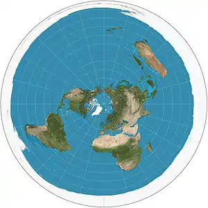
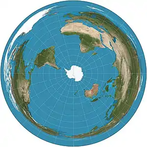
The azimuthal equidistant projection is an azimuthal map projection. It has the useful properties that all points on the map are at proportionally correct distances from the center point, and that all points on the map are at the correct azimuth (direction) from the center point. A useful application for this type of projection is a polar projection which shows all meridians (lines of longitude) as straight, with distances from the pole represented correctly. The flag of the United Nations contains an example of a polar azimuthal equidistant projection.

History
While it may have been used by ancient Egyptians for star maps in some holy books,[1] the earliest text describing the azimuthal equidistant projection is an 11th-century work by al-Biruni.[2]
The projection appears in many Renaissance maps, and Gerardus Mercator used it for an inset of the north polar regions in sheet 13 and legend 6 of his well-known 1569 map. In France and Russia this projection is named "Postel projection" after Guillaume Postel, who used it for a map in 1581.[3] Many modern star chart planispheres use the polar azimuthal equidistant projection.
Mathematical definition

A point on the globe is chosen as "the center" in the sense that mapped distances and azimuth directions from that point to any other point will be correct. That point, (φ1, λ0), will project to the center of a circular projection, with φ referring to latitude and λ referring to longitude. All points along a given azimuth will project along a straight line from the center, and the angle θ that the line subtends from the vertical is the azimuth angle. The distance from the center point to another projected point ρ is the arc length along a great circle between them on the globe. By this description, then, the point on the plane specified by (θ,ρ) will be projected to Cartesian coordinates:
The relationship between the coordinates (θ,ρ) of the point on the globe, and its latitude and longitude coordinates (φ, λ) is given by the equations: [4]
When the center point is the north pole, φ1 equals and λ0 is arbitrary, so it is most convenient to assign it the value of 0. This assignment significantly simplifies the equations for ρu and θ to:
Limitation
With the circumference of the Earth being approximately 40,000 km (24,855 mi), the maximum distance that can be displayed on an azimuthal equidistant projection map is half the circumference, or about 20,000 km (12,427 mi). For distances less than 10,000 km (6,214 mi) distortions are minimal. For distances 10,000–15,000 km (6,214–9,321 mi) the distortions are moderate. Distances greater than 15,000 km (9,321 mi) are severely distorted.
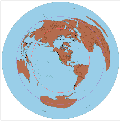
If the azimuthal equidistant projection map is centered about a point whose antipodal point lies on land and the map is extended to the maximum distance of 20,000 km (12,427 mi) the antipode point smears into a large circle. This is shown in the example of two maps centered about Los Angeles, and Taipei. The antipode for Los Angeles is in the south Indian Ocean hence there is not much significant distortion of land masses for the Los Angeles centered map except for East Africa and Madagascar. On the other hand, Taipei's antipode is near the Argentina–Paraguay border, causing the Taipei centered map to severely distort South America.
- Sample azimuthal equidistant projection maps. Red circles = 10,000 km; Purple circles = 15,000 km circle.
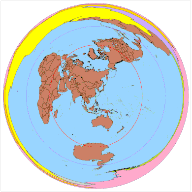 Map centered about Taipei, whose antipodal point is near the Argentina–Paraguay border.
Brazil · Paraguay · Argentina · Chile · Bolivia · Uruguay
Applications

Azimuthal equidistant projection maps can be useful in terrestrial point to point communication. This type of projection allows the operator to easily determine in which direction to point their directional antenna. The operator simply finds on the map the location of the target transmitter or receiver (i.e. the other antenna being communicated with) and uses the map to determine the azimuth angle needed to point the operator's antenna. The operator would use an electric rotator to point the antenna. The map can also be used in one way communication. For example if the operator is looking to receive signals from a distant radio station, this type of projection could help identify the direction of the distant radio station. In order for the map to be useful, the map should be centered as close as possible about the location of the operator's antenna.
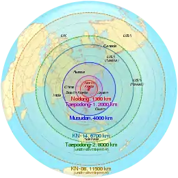
Azimuthal equidistant projection maps can also be useful to show ranges of missiles, as demonstrated by the map on the right.
See also
References
- SNYDER, John P. (1997). Flattening the earth: two thousand years of map projections. University of Chicago Press. ISBN 0-226-76747-7., p.29
- David A. KING (1996), "Astronomy and Islamic society: Qibla, gnomics and timekeeping", in Roshdi Rashed, ed., Encyclopedia of the History of Arabic Science, Vol. 1, p. 128–184 [153]. Routledge, London and New York.
- Snyder 1997, p. 29
- Snyder, John P.; Voxland, Philip M. (1989). An Album of Map Projections. Professional Paper 1453. Denver: USGS. p. 228. ISBN 978-0160033681. Archived from the original on 2010-07-01. Retrieved 2018-03-29.
External links
- Table of examples and properties of all common projections, from radicalcartography.net
- Online Azimuthal Equidistant Map Generator
- An interactive Java Applet to study the metric deformations of the Azimuthal Equidistant Projection.
- GeographicLib provides a class for performing azimuthal equidistant projections centered at any point on the ellipsoid.
- Animated US National Weather Service Wind Data for Azimuthal equidistant projection.
- Generate an Azimuthal equidistant projection from any point on Earth from ns6t.net.
