Oedometer test
An oedometer test is a kind of geotechnical investigation performed in geotechnical engineering that measures a soil's consolidation properties. Oedometer tests are performed by applying different loads to a soil sample and measuring the deformation response. The results from these tests are used to predict how a soil in the field will deform in response to a change in effective stress.

Oedometer tests are designed to simulate the one-dimensional deformation and drainage conditions that soils experience in the field. The soil sample in an oedometer test is typically a circular disc of diameter-to-height ratio of about 3:1. The sample is held in a rigid confining ring, which prevents lateral displacement of the soil sample, but allows the sample to swell or compress vertically in response to changes in applied load. Known vertical stresses are applied to the top and bottom faces of the sample, typically using free weights and a lever arm. The applied vertical stress is varied and the change of the thickness of the sample is measured.
For samples that are saturated with water, porous stones are placed on the top and bottom of the sample to allow drainage in the vertical direction, and the entire sample is submerged in water to prevent drying. Saturated soil samples exhibit the phenomenon of consolidation, whereby the soil's volume changes gradually to give a delayed response to the change in applied confining stresses. This typically takes minutes or hours to complete in an oedometer and the change of sample thickness with time is recorded, providing measurements of the coefficient of consolidation and the permeability of the soil.
Etymology
The word "oedometer" (/iˈdɒmɪtər/ ee-DO-mi-tər, sometimes /oʊˈdɒmɪtər/ oh-DO-mi-tər) is derived from Ancient Greek οἰδέω (oidéō, "to swell"), which also gave rise to the English word oedema.[1]
This should not be confused with the similar-looking but unrelated word "odometer", derived from Ancient Greek ὁδός (hodos, "path") which refers to a device to measure the distance travelled by a vehicle.[2]
History
Consolidation experiments were first carried out in 1910 by Frontard. A thin sample (2in thick by 14in in diameter) was cut and placed in a metal container with a perforated base. This sample was then loaded through a piston incrementally, allowing equilibrium to be reached after each increment. To prevent drying of the clay, the test was done in a room with high humidity.[3]
Karl von Terzaghi started his consolidation research in 1919 at Robert College in Istanbul.[3] Through these experiments, Terzaghi started to develop his theory of consolidation which was eventually published in 1923.
The Massachusetts Institute of Technology played a key role in early consolidation research. Both Terzaghi and Arthur Casagrande spent time at M.I.T. - Terzaghi from 1925 to 1929 and Casagrande from 1926 to 1932. During that time, the testing methods and apparatuses for consolidation testing were improved.[4] Casagrande's contributions to the technique of oedometer testing includes the "Casagrande method" to estimate the pre-consolidation pressure of a natural soil sample.[5] Research was continued at MIT in the 1940s by Donald Taylor.[6]
Both the British Standards Institute and the ASTM have standardised methods of oedometer testing. ASTM D2435 / D2435M - 11 covers oedometer testing by incremental loading. ASTM D3877, ASTM D4546 and AASHTO T216 also provide related procedures for conducting other similar tests for determination of the consolidation characteristics of soils.[7] BS 1377-5:1990 is the relevant British Standard for oedometer testing; the wider BS 1377 series also provides background information and best-practice advice on sample preparation for various geotechnical investigations.[8] There are also two ISO standards on oedometer testing: ISO 17892-5:2017 on incremental loading oedometer tests;[9] and BS EN ISO 17892-11:2019 covers various methods of soil permeability testing, including oedometer tests on saturated samples.[10]
Equipment

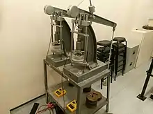
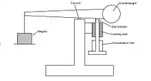
An oedometer is fundamentally made out of three components: a "consolidation cell" to hold the soil sample, a mechanism to apply a known pressure over the sample, and an instrument to measure the changes in the sample's thickness.[11]
The equipment required to perform an oedometer test is sometimes called an "oedometer test set". A typical inventory of an oedometer laboratory includes:[12]
- 1 x Bench
- 3 x Oedometers
- 3 x Cells, either 50mm or 63.5mm, or 75mm
- 3 x Dial gauges, either analogue, or digital
- 1 x Weight set
The consolidation cell is the part of the oedometer that holds the soil sample during a test. At the centre of the consolidation cell is a sample ring where the soil sample is held. The sample ring is typically shaped like a cookie cutter, with a sharp edge on one side, so the ring can be used to cut out a sample slice of soil from a larger block of natural soil. Two slices of porous stone, which fit snugly into the sample ring, provide water drainage to the soil sample while confining it mechanically. These components all fit in a larger cylinder, which has grooves to ensure alignment of the components, and provides water supply and drainage to external plumbing. A rigid loading cap sits on top of the soil sample to apply compressive loads to the soil.[11][13]
The loading mechanism of the oedometer applies a known compressive load, and therefore a known compressive stress since the diameter is fixed, to the soil sample. Most oedometers achieve this with a lever arm and a set of free weights: the free weights provide a known gravitational load, and the lever arm multiplies and transmits the load to the soil sample.[14]
Testing procedures

There are many oedometer tests that are used to measure consolidation properties. The most common type is the incremental loading (IL) test.[15]
Sample preparation
Tests are carried out on specimens prepared from undisturbed samples. A stiff confining ring with a sharp edge is used to cut a sample of soil directly from a larger block of soil. Excess soil is carefully carved away, leaving a sample with a diameter-to-height ratio of 3 or more. Porous stones are placed on the top and bottom of the sample to provide drainage. A rigid loading cap is then placed on top of the upper porous stone. For saturated soil samples, it is important to submerge the entire sample ring in water to prevent the sample from drying out.[15]
Incremental loading
This assembly is then placed into a loading frame. Weights are placed on the frame, imposing a load on the soil. Compression of the sample is measured over time by a dial indicator. By observing the deflection value over time data, it can be determined when the sample has reached the end of primary consolidation. Another load is then immediately placed on the soil and this process is repeated. After a significant total load has been applied, the load on the sample is decreased incrementally. Using a load increment ratio of 1/2 provides a sufficient number of data points to describe the relationship between void ratio and effective stress for a soil.[15]
Results
Oedometer tests provide engineers with very useful data about the soil being tested.
Consolidation Properties
- Preconsolidation pressure σ'p[16]
- The effective stress that marks the boundary between stiff and soft deformation response of a soil to loading
- Usually indicative of high loadings in the past from glaciers or eroded layers
- Recompression Index CR = Δe/Δlogσ'v[17]
- How the soil will change volume (settle) under loads less than the preconsolidation pressure
- Can be used to approximate swelling due to unloading
- Compression Index CC = Δe/Δlogσ'v[17]
- How the soil will change volume (settle) under loads greater than the preconsolidation pressure
- Duration of Primary Consolidation tp[18]
- Secondary Compression Index Cα = Δe/Δlogt[18]
- How the soil will change volume (settle) under a constant loading
See also
References
- "oedometer | Definition of oedometer in English by Oxford Dictionaries". Oxford Dictionaries | English. Retrieved 2019-04-06.
- "odometer | Definition of odometer in English by Oxford Dictionaries". Oxford Dictionaries | English. Retrieved 2019-04-06.
- Bjerrum, Laurits; Casagrande, Arthur; Peck, Ralph; Skempton, Alec. (1960). From Theory to Practice in Soil Mechanics. (p44) John Wiley & Sons, Inc.
- Bjerrum, Laurits; Casagrande, Arthur; Peck, Ralph; Skempton, Alec. (1960). From Theory to Practice in Soil Mechanics. (p6-7) John Wiley & Sons, Inc.
- "Coefficient of Earth Pressure at Rest", Geotechnical Correlations for Soils and Rocks, John Wiley & Sons, Inc., 2018-06-01, pp. 73–75, doi:10.1002/9781119482819.ch8, ISBN 9781119482819
- Taylor, Donald W. (1942). Research on Consolidation of Clays. Massachusetts Institute of Technology
- "ASTM D2435 / D2435M - 11 Standard Test Methods for One-Dimensional Consolidation Properties of Soils Using Incremental Loading". www.astm.org. Retrieved 2019-04-07.
- "BS 1377-5:1990 - Methods of test for soils for civil engineering purposes. Compressibility, permeability and durability tests – BSI British Standards". shop.bsigroup.com. Retrieved 2019-04-07.
- "BS EN ISO 17892-5:2017 - Geotechnical investigation and testing. Laboratory testing of soil. Incremental loading oedometer test". shop.bsigroup.com. Retrieved 2019-04-07.
- "BS EN ISO 17892-11:2019 Geotechnical investigation and testing. Laboratory testing of soil. Permeability tests". shop.bsigroup.com. Retrieved 2019-04-07.
- Sjursen, Morten Andreas; Dyvik, Rune. "Lab Test - Oedometer Test" (PDF). Norwegian Geotechnical Institute. Retrieved 2019-04-14.
- "Front Loading Oedometer Test Set". www.cooper.co.uk. Cooper Research Technology. Retrieved 5 September 2014.
- "Floating Ring Consolidation Cell". www.humboldtmfg.com. Retrieved 2019-04-14.
- "Soil Consolidation - Oedometers". www.pcte.com.au. Retrieved 2019-04-14.
- Terzaghi, Karl; Peck, Ralph; Mesri, Gholamreza (1996). Soil Mechanics in Engineering Practice (3rd Edition). (Article 16.9) Wiley-Interscience
- Terzaghi, Karl; Peck, Ralph; Mesri, Gholamreza (1996). Soil mechanics in Engineering Practice (3rd Edition). (Article 16.4) Wiley-Interscience
- Terzaghi, Karl; Peck, Ralph; Mesri, Gholamreza (1996). Soil mechanics in Engineering Practice (3rd Edition). (Article 16.6) Wiley-Interscience
- Terzaghi, Karl; Peck, Ralph; Mesri, Gholamreza (1996). Soil mechanics in Engineering Practice (3rd Edition). (Article 16.7) Wiley-Interscience